This page provides a tutorial on creating a Fire Tornado simulation with Chaos Phoenix in 3ds Max.
Overview
This is an Intermediate Level tutorial. Even though no previous knowledge of Phoenix is required to follow along, re-purposing the setup shown here to another shot may require a deeper understanding of the host platform's tools, and some modifications of the simulation settings.
Requires Phoenix 3.11.00 Official Release and V-Ray Next Official Release for 3ds Max 2015 or newer. You can download official Phoenix and V-Ray from https://download.chaos.com. If you notice a major difference between the results shown here and the behavior of your setup, please reach us using the Support Form.
The instructions on this page guide you through the process of creating a Fire Tornado effect using Phoenix and 3ds Max.
The Download button below provides you with an archive containing the end scene, as well as a Phoenix Render Settings preset that you can use to quickly set up the volumetric shading options for the fire tornado simulation.
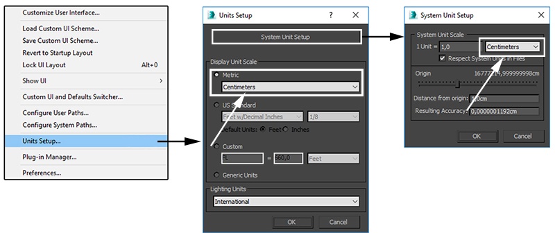
Units Setup
Scale is crucial for the behavior of any simulation. The real-world size of the Simulator in units is important for the simulation dynamics. Large-scale simulations appear to move more slowly, while mid-to-small scale simulations have lots of vigorous movement. When you create your Simulator, you must check the Grid rollout where the real-world extents of the Simulator are shown. If the size of the Simulator in the scene cannot be changed, you can cheat the solver into working as if the scale is larger or smaller by changing the Scene Scale option in the Grid rollout.
The Phoenix solver is not affected by how you choose to view the Display Unit Scale - it is just a matter of convenience.
The fire tornado effect we're creating is about 6 meters in height so we choose to view the units as Centimeters.
Go to Customize → Units Setup and set Display Unit Scale to Metric Centimeters.
Also, set the System Units such that 1 Unit equals 1 Centimeter.
Scene Layout
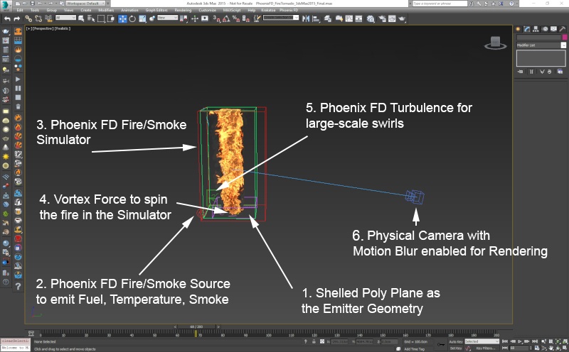
The final scene consists of the following elements:
- A shelled Poly Plane used as the source geometry for Smoke, Fuel and Temperature. An animated Noise modifier is applied to the plane to break-up the emission and produce interesting swirls.
- A Phoenix Fire/Smoke Source with the Poly Plane in its Emitter Nodes list. The Source is in Volume Inject mode and Noise is enabled for extra randomization.
- A Phoenix Fire/Smoke Simulator with some tweaks in the Grid, Dynamics, Fuel and Rendering rollouts. It's note-worthy that with this setup Burning is enabled under the Fuel rollout.
- A 3ds Max Vortex force responsible for creating the funnel. The position of the vortex force is animated which gives the tornado a more chaotic appearance.
- A Phoenix Turbulence force to break-up the fire and smoke even further. As the purpose of the turbulence is to create large-scale motion, its Size parameter is set to a rather high value and the Fractal Depth is reduced to 0 so the noise field has only 1 layer of details.
- A V-Ray Physical camera with minor tweaks for final rendering.
Scene Setup
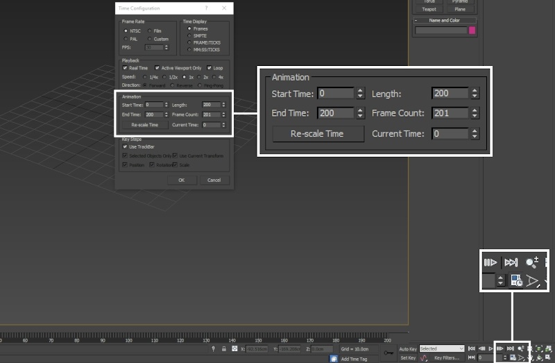
Set the Time Configuration → Animation Length to 200 so that the Timeline goes from 0 to 200.
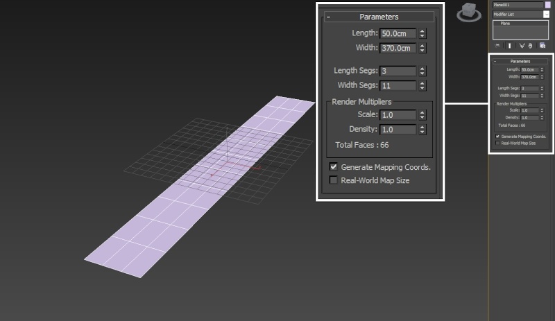
Create a Standard Primitives → Plane. The plane is used as the emission object for fuel, temperature and smoke.
Set its Length / Width to 50cm / 370cm and set the Length/Width Segments to 3/11.
In this example, the Plane is positioned at 0, 0, 0 in X, Y, Z.
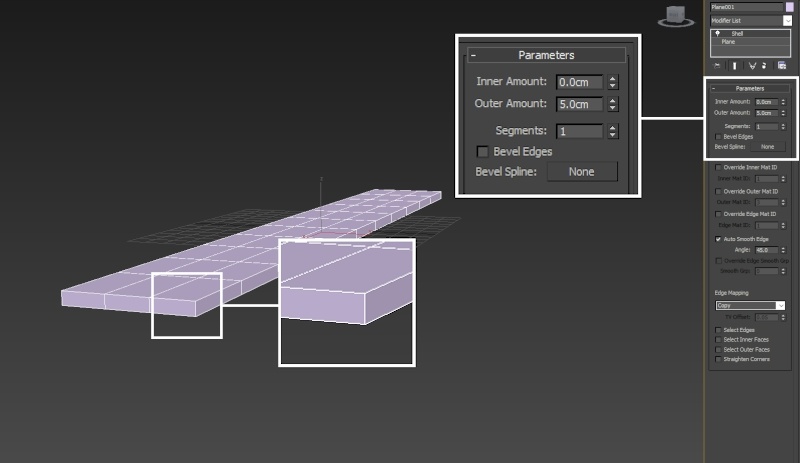
Apply a Shell modifier to the plane to give it some thickness and set the Outer Amount to 5.
Using open geometry or geometry with no thickness (such as the plane in this example) can give you unpredictable simulation results. Making sure that your geometry is clean is crucial for a smooth workflow. Phoenix (and many simulation packages in general) use a volumetric representation of the emission geometry for the simulation. The process of creating this volumetric representation is called voxelization. The algorithms responsible for voxelizing the geometry can fail when using open (with holes) or planar (no thickness) geometry.
The Shell modifier is applied here to turn the plane into what is essentially a very thin box. This is enough to sort out any possible problems with the voxelization at simulation time.
Phoenix Setup
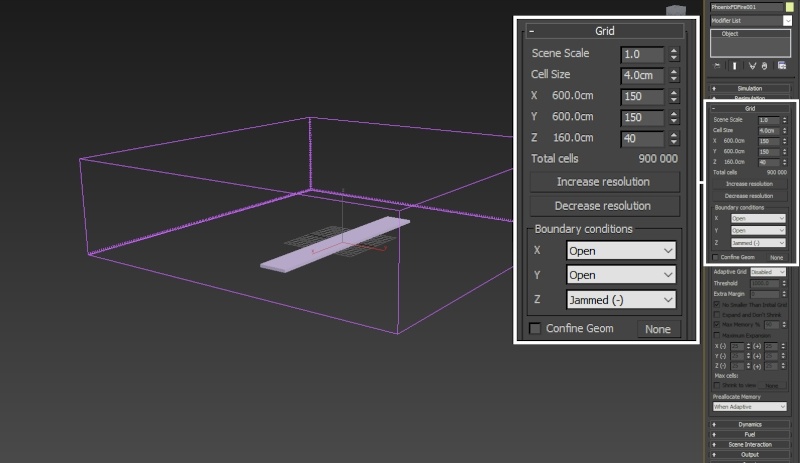
Create a Phoenix Fire/Smoke Simulator and set the Grid → Cell Size to 4.
Set the Size X/Y/Z to 150/150/40 respectively.
Set the Boundary Conditions: Z to Jammed ( - ). When a wall is Jammed (closed off, basically) the velocities inside the Simulator are calculated differently than in the situation where the wall is considered open. The emitted fluid will also collide with Jammed walls.
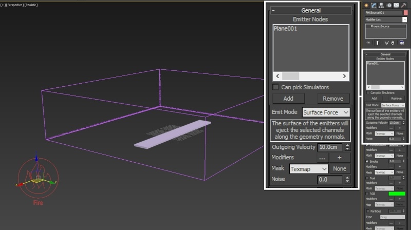
Create a Phoenix Fire/Smoke Source and add the shelled poly plane to the Emitter Nodes list by using the Add button.
Now that all the required elements for a smoke simulation are present ( (1) Emission Geometry, (2) Source and (3) Simulator ), we can run the simulation to see what we've got.
Here's how the simulation looks at the moment. Clearly this looks nothing like a fiery tornado so we need to make some changes.
Note how the smoke is going straight up instead of twisting the way a tornado would. We resolve this first by adding a 3ds Max Vortex force and tweaking its settings.
The Preview to the right is generated by using Tools → Preview - Grab Viewport → Create Preview Animation (Shift + V).
Phoenix provides a high-quality GPU Preview directly in the 3ds Max Viewport which can be enabled from Preview rollout of the Phoenix Simulator. To do so, go to the Preview rollout → GPU preview section → Enable in Viewport.
You may want to keep it disabled if you're working through a Remote Desktop connection or on a machine with an integrated graphics card.
Adding the Vortex Force
Create a Space Warps → Forces → Vortex force. Phoenix will automatically recognize and use it during the simulation unless you choose to put it in the Simulator → Scene Interaction → Exclude List.
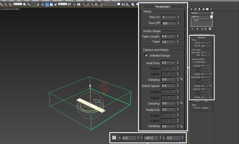
Set the Time Off to 200, or however many frames your simulation length is.
Set the Taper Length parameter to 0 - this parameter can be useful for controlling the height of the vortex but it tends to be easier to only use the options in the Capture and Motion section.
Set the Axial Drop and Orbital Speed parameters to 6.
Set the Radial Pull to 1.5.
To produce a funnel shape that doesn't spin outwards uncontrollably or collapse in on itself, you need to find a balance between the Radial Pull and the Orbital Speed. The provided values work for this example but if you are using a different setup, you may need to tweak the parameters until you get the desired shape.
Make sure to rotate the Vortex force gizmo 180 degrees in Y such that the arrow is pointing up in the +Z direction.
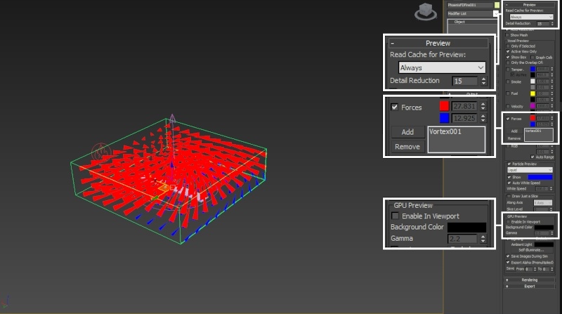
Phoenix allows you to preview the velocities that an external force will add into the simulation. Because the Forces preview feature is fully interactive and does not require you to run a simulation, this can be especially useful when tweaking the parameters.
To specify the force you'd like to preview, go to the Simulator → Preview rollout and Enable Forces under the Voxel Preview section.
Use the Add button to include the Vortex force into the Forces Preview List. If the grid of arrows is too dense, increase the Detail Reduction parameter - this will give you a sparser preview of the velocities represented as arrows.
Simulator → Preview → GPU Preview needs to be disabled for the Force preview to show up.
Here's how the simulation looks now. This is going in the right direction.
We animate the position of the Vortex Force so the smoke and fire don't spin around a single static point in space - this should give the tornado a more chaotic appearance.
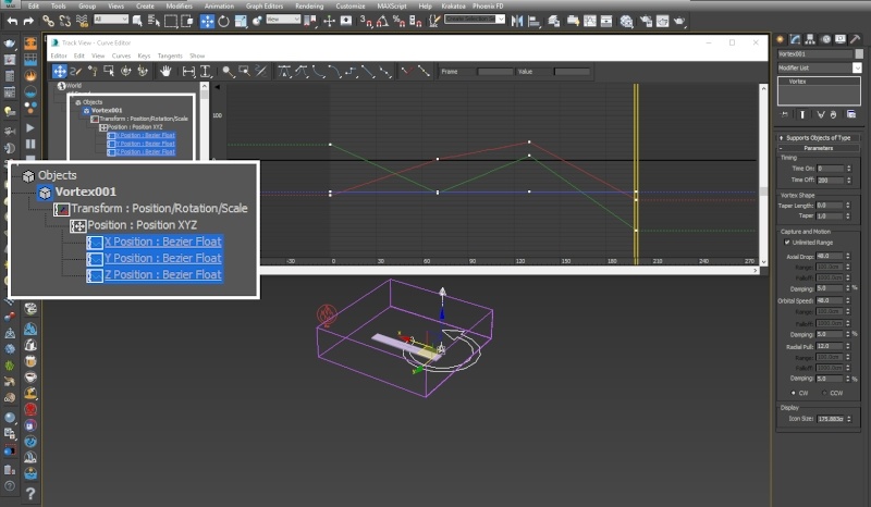
Select the Vortex force and animate its position such that it moves in the XY plane inside the Simulator.
Here are the exact key-frames in case you'd like your setup to be identical to this tutorial. Also, set the tangents for the animation curves to Linear inside the Curve Editor. The default interpolation is Ease-In / Ease-Out which would cause to vortex to accelerate and decelerate unnaturally.
Frame 0:
X: -78
Y: 35
Z: -70
Frame 70:
X: 2
Y: -73
Z: -70
Frame 130:
X: 40
Y: 10
Z: -70
Frame 200:
X: -88
Y: -156
Z: -70
Let's also enable the Adaptive Grid option so we can see how the simulation is progressing.
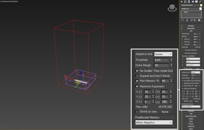
Select the Phoenix Simulator and open the Grid rollout.
Set the Adaptive Grid option to Smoke. The Adaptive Grid allows the container to resize on-demand as the simulation progresses, saving you a lot of time. Instead of calculating a giant grid from the start, the specified channel is tracked (Smoke in this case) and the grid is automatically resized around it.
Enable Maximum Expansion and set the X / Y / Z dimensions according to your needs (for this example, the exact values are on the picture to the right). Because the Z axis is Jammed in the negative Z direction, the Z(-) field is left at 0.
Set the Extra Margin to 10 - this option allows the adaptation to keep a number of voxels close to the walls as a buffer zone and expand the grid earlier than usual. This can be especially useful when simulating fast-moving objects or explosions as it allows the Simulator to expand before any clipping occurs.
Here's how the simulation looks after the animation on the Vortex force.
We are trying to make a Fiery Tornado simulation but fire is only present right at the bottom of the Simulator. To deal with this, we will use the Phoenix Fire Source to emit Fuel. Once Fuel is present in the Simulator, we can enable burning which will consume the emitted fuel and produce more fire.
Adding Fuel and Enabling Burning
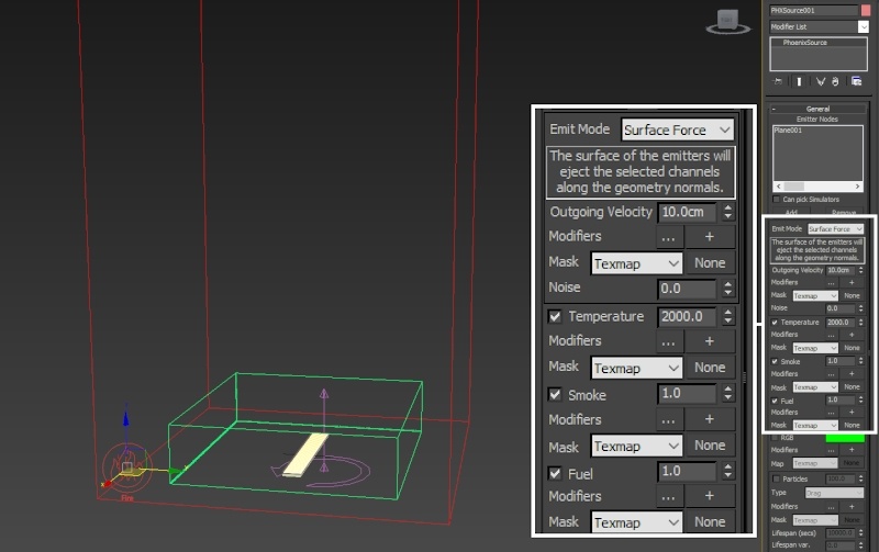
Select the Phoenix Source and enable the emission of Fuel.
Fuel is a required component for the simulation of burning. Once it comes into contact with the Temperature channel, it will ignite and produce more temperature and smoke based on the settings specified in the Fuel tab of the Simulator.
Select the Phoenix Simulator and open the Fuel tab.
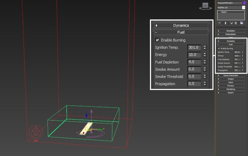
Select Enable Burning. This will tell the Simulator to convert the Fuel emitted by the Source into temperature and smoke based on the options below.
Set Ignition Temp. to 301. The ignition temperature specifies the minimum Temperature channel value that will ignite the fuel. Don't set this below 301 - 300 is the ambient temperature of the Simulator - if you do this, the Fuel will ignite instantly upon emission. You can find out more about Phoenix Grid Channel Ranges here.
Set Energy to 10 - the energy parameter controls how much Temperature is created by the process of burning.
Set Fuel Depletion to 4 - the higher this parameter is, the faster the fuel will burn out. Think of it this way - a piece of rubber can burn for a long time while a similarly sized piece of paper will last much shorter before turning into ash.
Set Smoke Amount, Smoke Threshold and Propagation to 0. The Smoke Amount and Threshold govern the emission of Smoke during the process of burning. We're not interested in creating smoke with this simulation so we disable it.
Propagation controls the strength of expansion of the volumes as a consequence of the ignition. An explosion would have a much higher propagation rate (the fireball will expand much further) than a burning match.
Here's the simulation with Fuel emission and Burning enabled.
To deal with the uniform appearance, we'll make a few changes to the Phoenix Source and the Phoenix Simulator.
Tweaking the emission
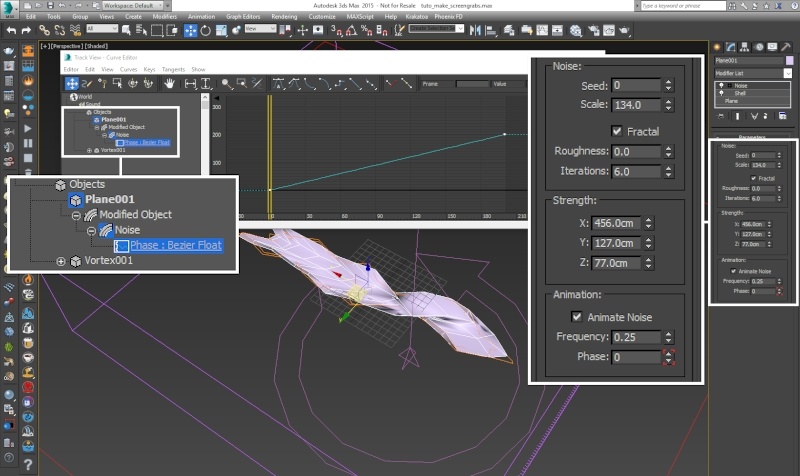
Add a Noise modifier to the shelled Poly Plane.
Set the Scale to 134, and the X/Y/Z Strength to 456 / 127 / 77.
Enable Fractal and leave the Roughness to 0 and the Iterations to 6.
Make sure to Enable the Animate Noise option.
You may also open the Graph Editors → Track View - Curve Editor and set the tangents for the Phase parameter to Linear.
Make sure to move the Simulator down in the Z axis to accommodate for the deformations of the plane.
In this example, the Phoenix Simulator is positioned at 0, 0, -50 in X, Y, Z.
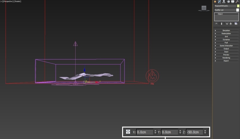
Here's the simulation with the Noise modifier applied to the shelled plane. It's adding some nice break-up in the emission.
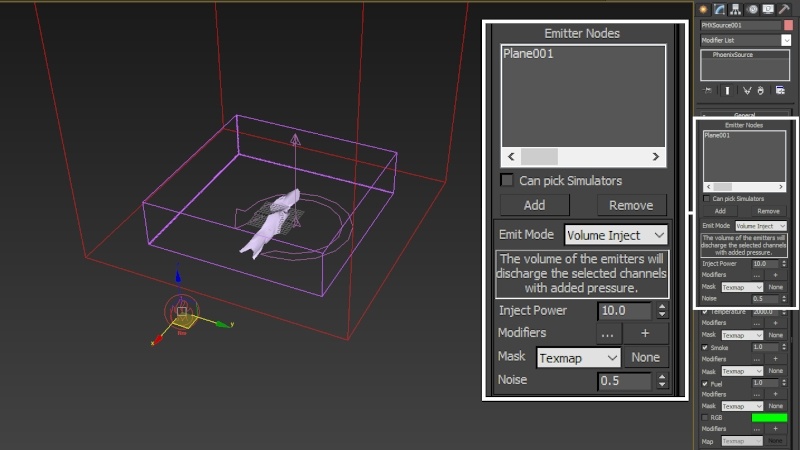
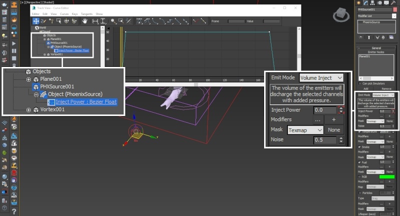
Select the Phoenix Source and set the Emit Mode to Volume Inject. The Volume Inject mode emits fluid into the container with pressure such that expansion occurs immediately after emission. This will further randomize the fire right at the source.
Set the Noise to 0.5. The Noise parameter acts as a random multiplier for the Inject Power.
Animate the Inject Power parameter:
Frame 1: 0
Frame 5: 50
Frame 177: 50
Frame 184: 0
You could omit this step in your setup. The animation is here for the purpose of letting the fire disappear at the end of the simulation.
Here's how the simulation looks with those changes.
Setting the mode to Volume Inject instead of Surface Force allows the fluid to follow the vortex force more closely. Notice how the twisting of the smoke at the top of the simulator is more pronounced now.
Phoenix Simulator Settings
Now that we've got Fuel, Temperature and Smoke injected into the simulation and carried by the Vortex force, the fiery tornado is finally starting to take shape.
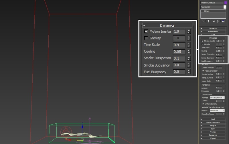
One major issue to address is that the smoke can be clearly seen travelling straight up. This is caused by the Gravity setting in the Dynamics tab. With Fire/Smoke Simulations, cold smoke (Temperature lower than 300 Kelvin) falls down and hot smoke rises up. This is causing the funnel of the tornado to break-up in an unnatural way. There are 2 ways to go about fixing this:
- You can try increasing the Axial Drop / Orbital Speed / Radial Pull parameters on the Vortex Force to counteract gravity. This would likely be the 'physically correct' way to go about doing this - the vortex should be strong enough to have full influence over the trajectory. However, this could also turn into a time-consuming endeavor.
- You can simply disable Gravity.
We go with the second approach.
Uncheck the tickbox to the left of Gravity to disable it.

Gravity Disabled
Gravity Disabled and Vortex Force hidden so it doesn't affect the simulation
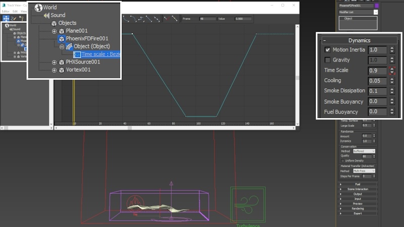
Set Time Scale to 0.9 to marginally slow down the simulation. This will give it a more epic appearance.
Smoke Dissipation should also be increased a bit. Set it to 0.1.
The dissipation of the smoke allows for interesting details to form while the smoke channel is carried through the cells of the simulator by the velocities present in the simulation.
Here's the simulation with Time Scale at 0.9 and Smoke Dissipation at 0.1.
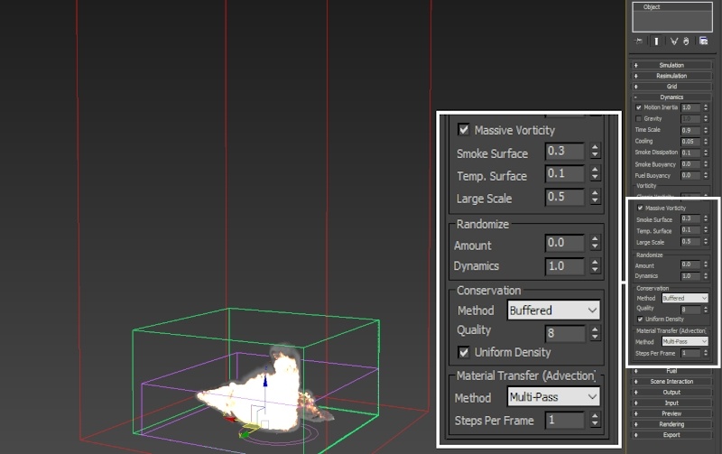
Set the Conservation Mode to Buffered.
The Buffered conservation mode is ideal for fire simulations because it tends to give the most detail. It appears as if it 'chops up' the fluid as it is transferred through the cells.
From this step onward the Fire Multiplier in the Rendering rollout → Volumetric Options...button → Fire has been reduced to 0.02 to make it easier to see what's going on in the preview videos below.
There is an entire section dedicated to the Volumetric Shading settings for the fire tornado - this is done merely for the sake of preview. If you'd like yours to look the same, reduce the Fire Multiplier to 0.02.
Buffered, Quality: 8 (default)
Buffered, Quality: 80
Disable Uniform Density and Set the Quality to 80.
Uniform Density controls whether the mass of the fluid is considered during the calculation. The mass is calculated as the inverse of the temperature - hot fluid is lighter and cold fluid is heavier. Since we disabled Gravity anyway, this won't do us any good. Disabling should save some time during the simulation.
The Conservation Quality controls how accurately the fluid is transferred through the cells of the Simulator. When this value is low, some of the fluid is lost along the way due to the nature of how grid-based simulations work.
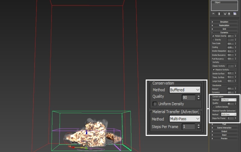
Uniform Density disabled and Conservation Quality at 80.
As can be seen here - not much of a difference, if any at all.
Increase the Steps Per Frame to 3.
You'll notice that the smoke funnel is now much wider. This is caused by the Conservation Quality that we set to 80 earlier which is now applied 3 times over the course of a single frame. This causes the smoke to be transferred much further along the velocities created by the vortex force.
In the next step we increase the strength of the Vortex Force to both reduce the width of the funnel and make the simulation more violent.
Select the Vortex Force and increase the Axial Drop, Orbital Speed and Radial Pull parameters. How strong you make those is entirely up to your artistic judgement.
In this example, we set them to the following values:
Axial Drop: 48
Orbital Speed: 48
Radial Pull: 12
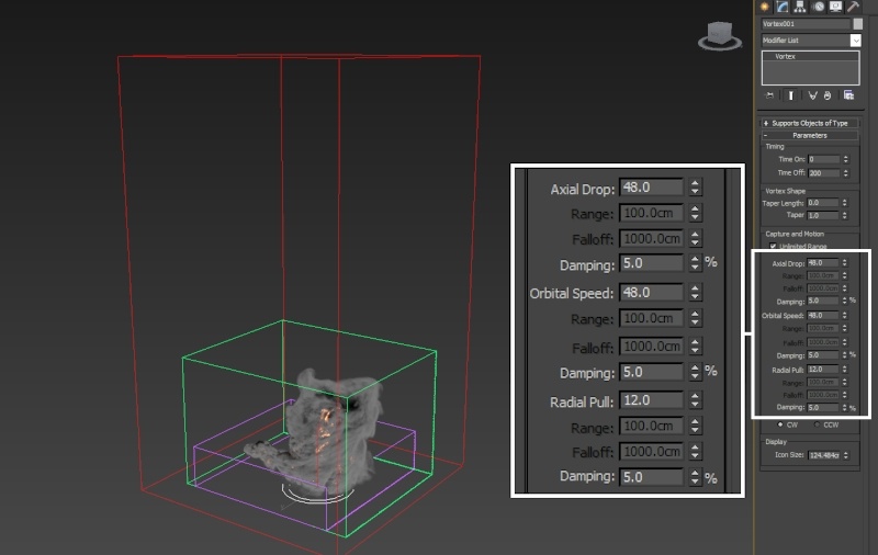
Axial Drop: 24, Orbital Speed: 24, Radial Pull: 6
Axial Drop: 48, Orbital Speed: 48, Radial Pull: 12
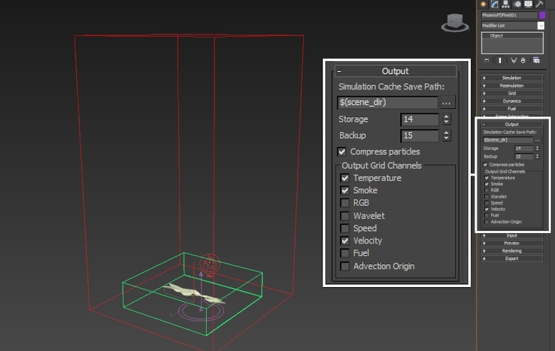
Lastly, open the Output rollout of the Simulator and enable the export of Velocity.
The Velocity channel is required when rendering with Motion Blur so V-Ray knows in what direction to 'stretch' the fluid.
Phoenix Render Settings
Let's make some tweaks to the Volumetric Shader before proceeding with the rest of the tutorial.
Open the Phoenix Simulator → Rendering rollout and click the Volumetric Options button. The Volumetric Options contain the shading parameters for rendering fire and smoke. You can think of that window as the Phoenix Volumetric Shader.
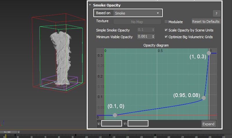
In the Smoke Opacity rollout, set Based on to Smoke. The Opacity Diagram below should now become active - it is used to control the thickness of the smoke.
The difference between the Smoke and Simple Smoke option is that when the Opacity is set to use the Smoke channel, the Opacity Diagram below can be used to make changes to the way the Smoke is rendered by using the opacity curve. With Simple Smoke, you get a single Simple Smoke Opacity multiplier that acts as if the Based on was set to Smoke and the curve below was completely straight, going from (0, 0) on the left to (1, whatever value Simple Smoke Opacity is ) on the right. To summarize: Based on: Smoke gives you access to a curve which can be used to control the thickness based on the value of the Smoke channel for a given voxel while the Simple Smoke provides a single uniform multiplier only.
The Opacity Curve in the diagram below is tweaked as follows:
Point 1: (0.1, 0)
Point 2: (0.95, 0.08)
Point 3: (1.0 , 0.3)
This change is essentially removing all the sparse smoke. If you want to get a clean preview of what your changes are doing to the Smoke, you can go to the Fire rollout and set the Based on option to Disabled to isolate the Smoke.
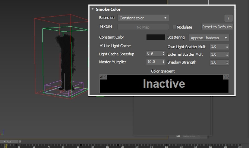
The Constant Color parameter in the Smoke Color rollout is set to RGB: (1, 1, 1), with a Master Multiplier of 1. Those values are an artistic choice entirely - feel free to tweak them as you see fit.
Open the Fire rollout.
The Color and Intensity Ramp is what will make or break this Fire Tornado effect. You should take the time to tweak the colors and the intensity curve until you're satisfied with the result in the Viewport.
You can see the settings for the final render in the image to the right. The curve has been tweaked such that there's a spike in the intensity in the 700 to 1500 temperature range.
Emit Light is disabled for our scene to speed up the rendering as the fire tornado is the only object in the image. In your scene, however, you may need to enable this if you want the fire to illuminate the objects in your scene.
We've provided you with a preset called PhoenixFD_FireTornado_Render.tpr which you can load from the Rendering rollout → Render Presets... button → Load from File... in case you'd like your setup to be completely identical.
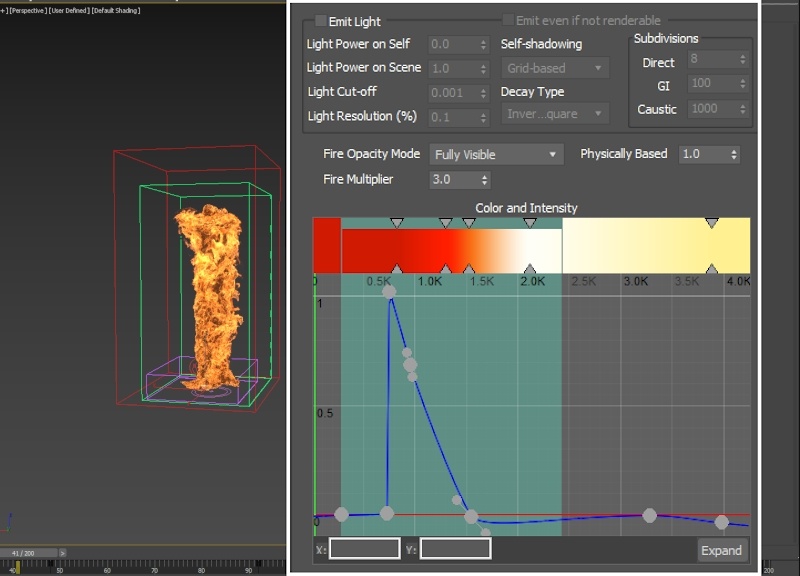
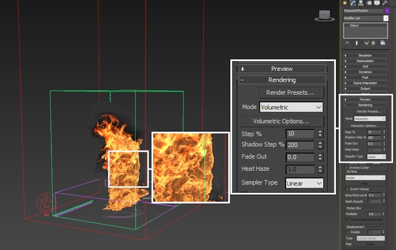
Depending on your setup, you may notice quite a bit of noise in the fire if you start tweaking the curve such that sharp spikes are present, as in the image to the right.
To resolve this, you can reduce the Step% parameter in the Rendering rollout of the Simulator. For this example, the Step% is reduced to 10.
Note that reducing the Step% will increase the time it will take for V-Ray to render your image.
You may also set the Sampler Type to Spherical if you notice artifacts in the fire at render time.
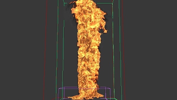
Here's the entire 200 frames of the simulation with all the tweaks we've done so far:
Adding Phoenix Turbulence for Large-Scale Swirls
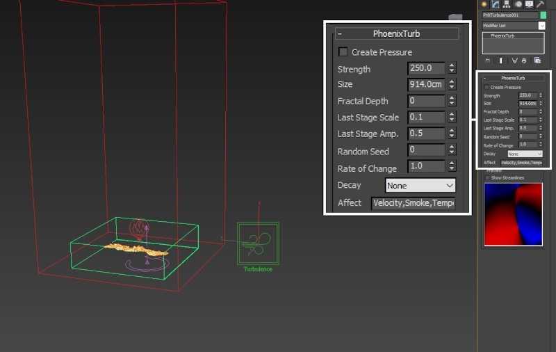
Create a Helpers → Phoenix FD → PHXTurbulence.
Set the Strength to 250 and the Size to 914.
Reduce the Fractal Depth to 0.
The Turbulence is used to break-up the fire even further. Please check the comparison images below.
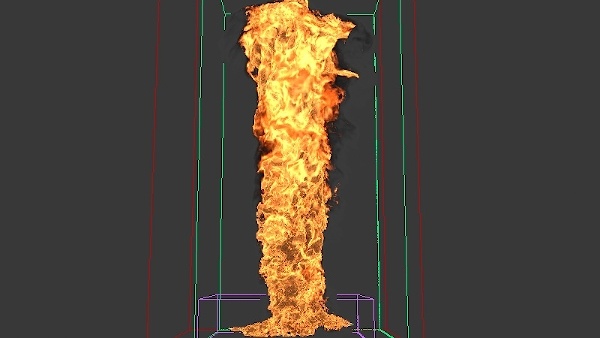
Without turbulence
With turbulence
Animating the Time Scale for Bullet-Time Effect
This section of the tutorial is optional. You may skip to the Rendering section below if you're not interested in re-creating the effect to the right.
To create the bullet-time effect, open the Dynamics tab of the Phoenix Simulator and animate the Time Scale parameter as follows:
Frame 1: 0.9
Frame 48: 0.9
Frame 92: 0.1
Frame 117: 0.1
Frame 150: 0.9
The Time Scale is a global multiplier for the dynamics of the Simulator. Reducing it will uniformly scale down all sources of velocity in the simulation.
Consider settings the tangents to Linear in the Curve Editor - the default ease-in / ease-out may look unnatural.
Camera Settings
Go to Create → Cameras → V-Ray → V-Ray Physical Camera. The settings for the camera are as follows:
Position:
X: -27
Y: 2625
Z: 190
Target Position:
X: -50
Y: -40
Z: 615
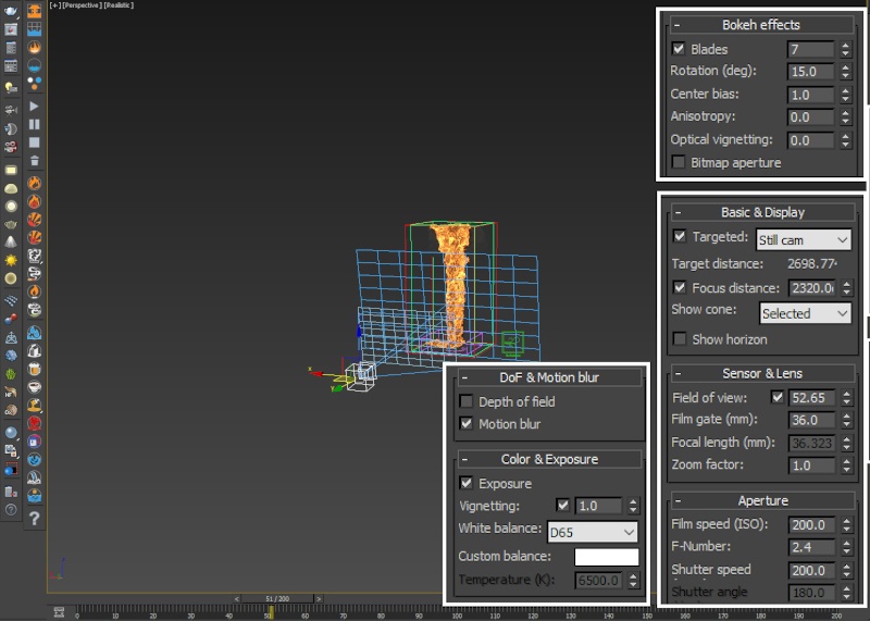
Focus Distance is enabled and set to 2320. You may try rendering the simulation with Depth of Field - setting this up should give you a good starting point.
Sensor & Lens → Field of view is modified to 52.65.
In the Aperture section, the F-Number is set to 2.4 and the Shutter speed to 200 and the ISO to 200.
Under DoF & Motion blur, Motion blur is enabled.
You need to enable Velocity Channel export under the Phoenix Simulator → Output tab when rendering a simulation with Motion Blur. V-Ray uses the Velocity Channel to figure out the direction in which the fluid should be blurred.
Under Color & Exposure, Vignetting is enabled and the Value left to its default of 1. The Vignetting effects darkens the outer edges of the image.
In the Bokeh effects tab, the Blades option is enabled and set to 7, with a Rotation of 15.
Render Settings
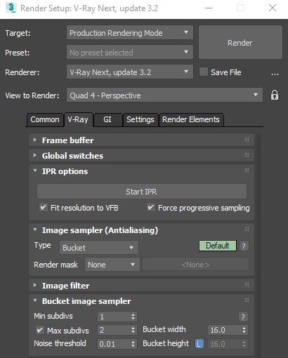
In the Render Setup Tab:
The Image sampler Type is set to Bucket.
The Max subdivs are set to 2.
The Bucket width is set to 16.
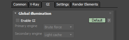
The Global illumination is disabled.
For the final render, some corrections are made in the V-Ray Frame Buffer.
Exposure options are enabled and the Exposure is set to 0.2 and the Contrast to 0.16.
White Balance is also enabled and the Temperature is set to 6700.
Hue/Saturation is enabled and the Saturation is set to 0.04.
Experiment with the Curve to achieve the desired look.
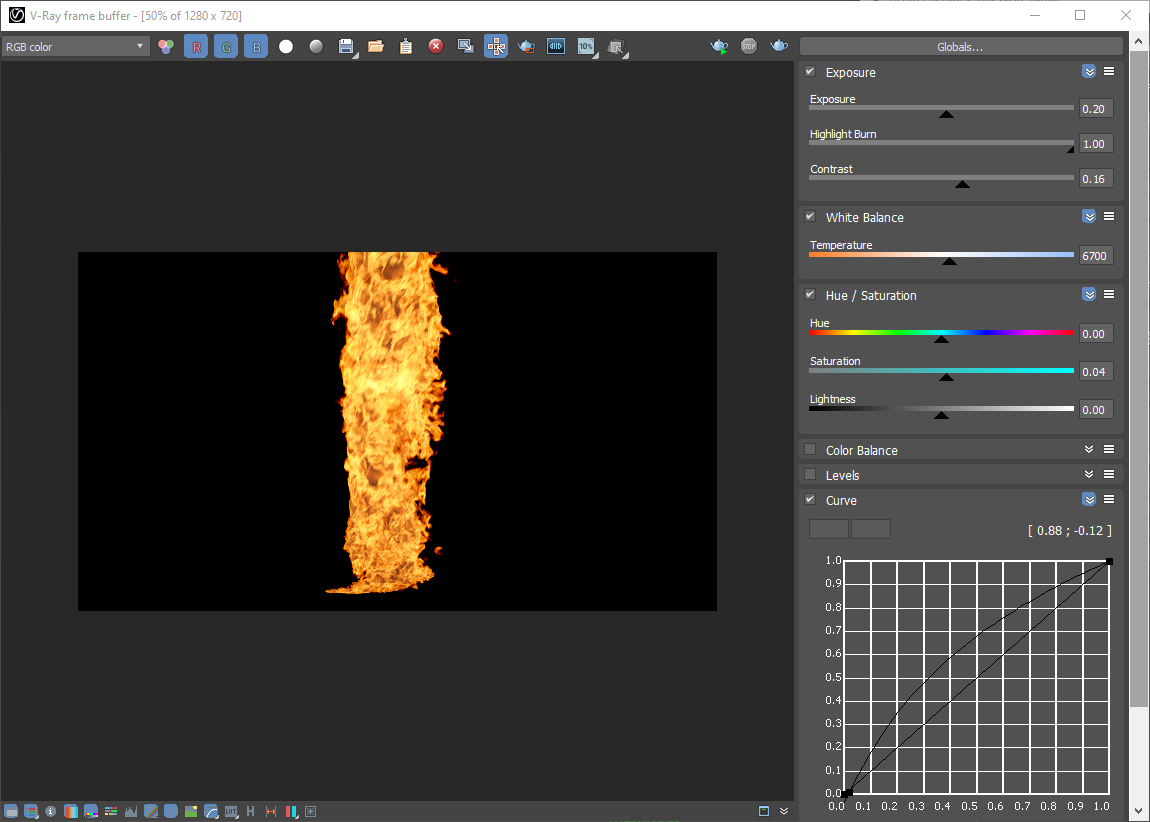
And here is the final result.