Overview
Discharge Modifiers allow you to tweak parameters of the source such as the general discharge strength or the amount of emitter Smoke, Fuel, etc. These parameters can be altered based on properties of the emitter geometry that vary for each voxel on the surface or in the volume. For example, alterations can be based on the direction of the normals, the velocity of each emitter voxel, the position in world or grid space, etc. A discharge modifier can also add random variation to the affected parameter across the surface or throughout the volume of the emitter object.
Discharge Modifiers can be linked in chains, modifying the same parameter, and can also be reused for modifying several parameters at once with a single Discharge Modifier. When chaining Discharge Modifiers, their effect is multiplied.
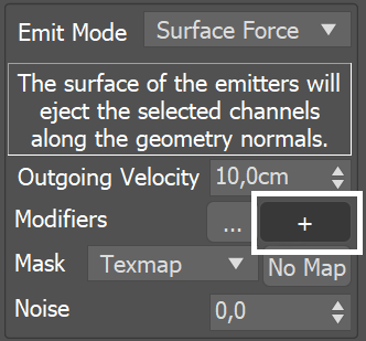
UI Path: ||Select Fire Source|| > Modify Panel > General rollout > Mod + button
(Create a new Discharge Modifier)
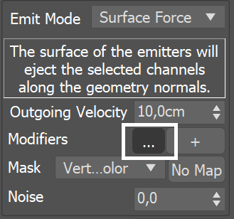
UI Path: ||Select Fire Source|| > Modify Panel > General rollout > Mod ... button
(Link an existing Discharge Modifier)
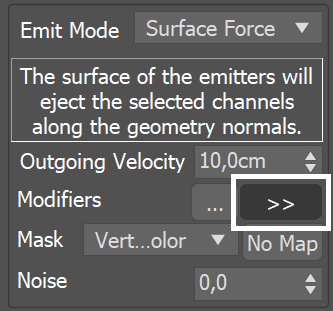
UI Path: ||Select Fire Source|| > Modify Panel > General rollout > Mod >> button
(Go to an existing Discharge Modifier)
Parameters
A chain of modifiers modulate the emission using properties of the emission geometry at the point of interaction with the simulator. A ramp control is used to remap from the value of the specified property (i.e. Speed) to a multiplier ranging from 0.0 to 1.0.
Next | dmodnext – Specifies the next modifier in the chain. You can create a new Discharge Modifier, link to an existing one, or unlink a Discharge Modifier.
Modify [parameter] by | affectby – This is the property of the emitter that will be used to modify the Source's parameter where the Discharge Modifier is plugged. The parameter could be Outgoing Velocity, Inject Power, Brush Effect, Temperature, Smoke, Fuel, RGB, etc. The value of each parameter is mapped to the horizontal X-axis of the diagram. Along the Y-axis is the strength of the discharge. Each entry from the list below has a certain range that you should watch out for, e.g. some values range from -1 to +1 along X, while others range from 0 to a few hundred. You can find out more information about the usual ranges of Phoenix channels on the Grid Channel Ranges and the Particle Channel Ranges pages:
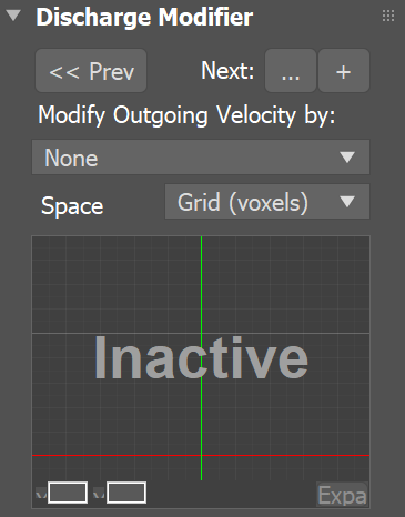
- None – Disables the Discharge Modifier.
- Random – A random number in the interval [0,1] will be assigned to each voxel of the emitter.
- Position X/Y/Z – The coordinates of the voxel will be used. In Grid space, the coordinates inside the simulator will be used and will be normalized to the interval [0,1]. In Object space, the coordinates inside the geometric object will be used and will be normalized to the interval [0,1].
- Normal X/Y/Z – The surface normals of the geometry will be used in the interval [-1,+1]. Note that this will always return 0 if the emitter is a particle system.
- Velocity X/Y/Z – The velocity of the emitter's voxel will be used. This will work when the emitters are particles and meshes, and in case of meshes it will work for any translating, rotating, scaling, and rigged geometries, as the velocity of each voxel of these geometries will be calculated by Phoenix and used by the Discharge Modifier. Note that this value may vary from several hundred to over a thousand and can be negative depending on the velocity's direction. The velocity is in the scale of the selected Space - in Grid space it will be in voxels/sec, and in World or Object space it will be in world/object units per second.
- Speed – The speed of the emitter's voxel will be used. This will work when the emitters are particles and meshes, and in case of meshes it will work for any translating, rotating, scaling, and rigged geometries, as the velocity of each voxel of these geometries will be calculated by Phoenix and used by the Discharge Modifier. Note that unlike Velocity X/Y/Z which is a direction broken down to the X, Y and Z components, Speed is the total velocity amount and is always positive. The speed is in the scale of the selected Space - in Grid space it will be in voxels/sec, and in World or Object space it will be in world/object units per second.
- Particle Age – The age of each emitting particle will be used. Note that this will work only when you emit fluid from particle systems. It will always return 0 when emitting from meshes and shapes. This value maps along the X diagram axis from 0 and is always positive.
- Particle Size – The size of each emitting particle will be used. Note that this will work only when you emit fluid from particle systems. It will always return 0 when emitting from meshes and shapes. This value maps along the X diagram axis from 0 and is always positive. The size is in the scale of the selected Space - in Grid space it will be in voxels, and in World or Object space it will be in world/object units.
Space | affectspace – The coordinate system of the Modify [parameter] by option:
- Object (units) – The modifying parameter will act in the coordinate system of the emitter object. If the object moves or rotates, it will always keep emitting from the same areas.
- Grid (voxels) – The modifying parameter will act in the simulator's coordinate system. This way you can make objects emit when they enter a certain area of the simulator and if the simulator moves or rotates, the area will move along with the simulator.
- World (units) – The modifying parameter will act in world coordinate system. This way you can make objects emit only in certain areas of the scene. If you use the normals to modify the discharge, in world space you could make an object emit only upwards regardless of how it rotates or where it moves.
You can use the following controls to edit the graph:
Double click – Creates a new point or changes an existing one.
Left button drag over a point – Moves the point. If several points were selected beforehand, they will move the same amount.
Left button drag over several points – Selects several points.
Middle button drag over the background – Drags the visible area. If the Shift key is pressed, scales the diagram in the corresponding direction.
Mouse wheel – Zooms in/out.
Mouse wheel near the borders of the control – Zooms in/out only along X or only along Y.
Right click – Displays a drop-down menu where you can add a point, edit or delete a selected point, fit the entire diagram into the view or reset to the default state. If multiple points are selected, they can be edited simultaneously.
Backspace – Deletes the selected points.
Example: Diagram Usage
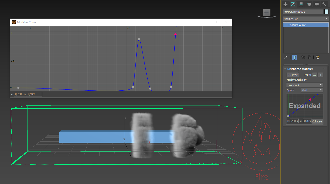
In the following setup, the Smoke value is modified by the position of each voxel along the X-axis in Gird coordinates. Note that in Grid Space, the coordinates will be normalized between 0 and 1, so no matter what the size of the simulator is, the diagram will rescale its function over the length of the simulator box. Along the vertical Y axis of the diagram is the effect of the discharge modifier, in this case - the amount of smoke.
Note that if you are simulating using Adaptive Grid and you want a discharge modifier by position to apply its effect always in the same position regardless of how the grid resizes, then you should change the Space to World and adjust the horizontal scale and position of the diagram so that it maps to the actual world coordinates.
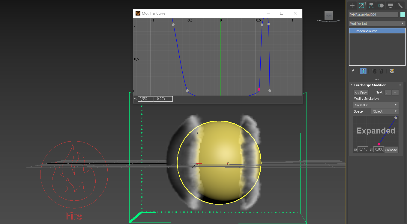
Another example is the following setup where the normals of the geometry are used to emit smoke. In this case, the normals are used in Object Space, so even if the object starts rotating, it would emit from the same areas. Note that the valid values for normals range from -1 to 1, instead of just 0 to 1. This way the negative values denote normals which point along the negative axis (in this case, to the left of the sphere), while the positive point along the axis direction from the object's transform (in this case, to the right of the sphere). In this example, the normal along the positive axis allows Smoke emission only when the normal's length along the object Y axis is between about 0.6 and 0.7, which means only from such normals which are at an angle and are neither horizontal nor vertical:
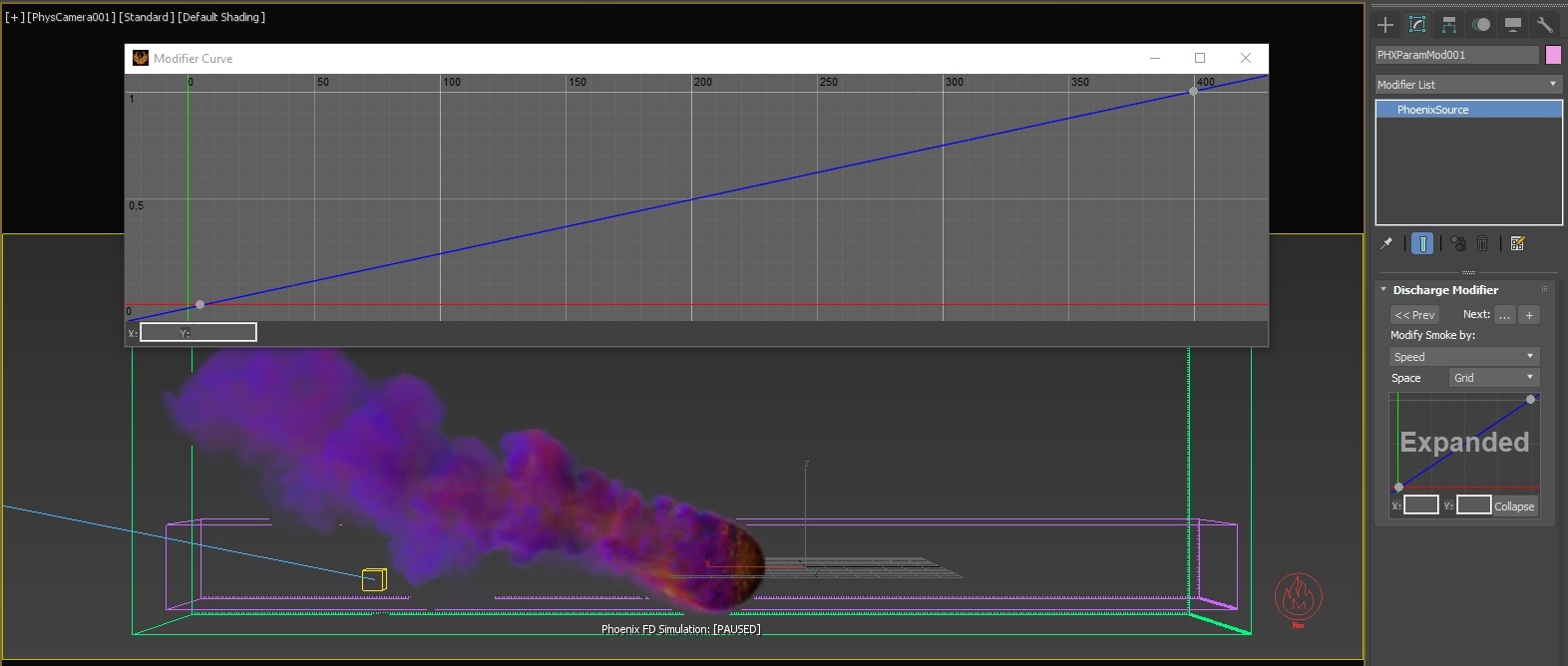
The following setup shows an accelerating ball which begins to emit smoke when it starts moving and emits denser smoke the faster it moves. The discharge modifier is set to the Smoke channel and the emission is set to Surface Force. This way the Surface Force will emit velocity out of the sphere during the entire sequence, but the smoke will get denser the faster the geometry moves and in the end when the geometry stops again, the emitted smoke density will go back to 0. You can check the range of the velocity value in the Simulation rollout's Cache File Content box - in this case the discharge modifier reaches the densest smoke emission when the speed goes above 400 and the emission starts when the speed goes above 5, so that a static object would not emit. These value are laid out on the horizontal axis, while the smoke density is mapped to the vertical axis of the Modifier Curve. Also note that the example uses Speed in Grid Space, but if you have a simulator connected to the geometry and moving, then it would be better to use World Space. The smoke in this example is colored by Speed as well: