The instructions on this page guide you through the process of creating burning boxes, using thinkingParticles and Chaos Phoenix for 3ds Max.
Overview
This is an Advanced Level tutorial. The workflow for setting up the shot, and the Phoenix settings involved in the simulation are explained in detail. However, creating a production quality shot of a similar nature may require some tweaks to the lighting, materials and/or the Phoenix simulation. An understanding of thinkingParticles is beneficial but not required.
In this tutorial we demonstrate how to work with thinkingParticles in tandem with Phoenix. We set up a burning boxes scene with thinkingParticles which make a disintegrating effect of the burning paper boxes. The Phoenix's Fire/Smoke Source picks up tP particles and uses those paper box fragments as a source of the fire/smoke. We also set up materials for realistic burning effect. With some further tweaks, we create burning boxes.
This simulation requires thinkingParticles 6, Phoenix 4 Official Release and V-Ray Next Official Release for 3ds Max 2015 at least. You can download official Phoenix and V-Ray from https://download.chaos.com. If you notice a major difference between the results shown here and the behavior of your setup, please reach us using the Support Form.
The Download button below provides you with an archive containing the start and end scenes.
Units Setup
Scale is crucial for the behavior of any simulation. The real-world size of the Simulator in units is important for the simulation dynamics. Large-scale simulations appear to move more slowly, while mid-to-small scale simulations have lots of vigorous movement. When you create your Simulator, you must check the Grid rollout where the real-world extents of the Simulator are shown. If the size of the Simulator in the scene cannot be changed, you can cheat the solver into working as if the scale is larger or smaller by changing the Scene Scale option in the Grid rollout.
The Phoenix solver is not affected by how you choose to view the Display Unit Scale - it is just a matter of convenience.
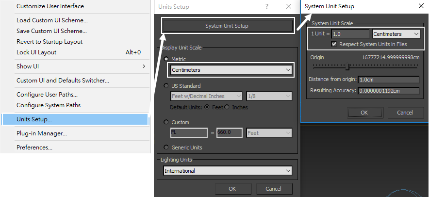
Go to Customize → Units Setup and set Display Unit Scale to Metric Centimeters.
Also, set the System Units such that 1 Unit equals 1 Centimeter.
Scene Setup
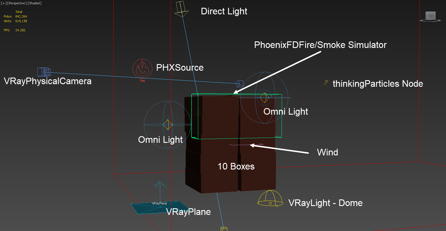
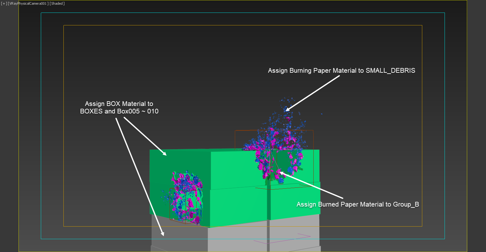
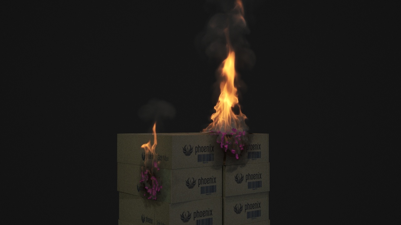
The final scene consists of the following elements displayed on the picture:
Total of ten pre-fragmented Boxes;
A Phoenix Fire/Smoke source (PHXSource) with the thinkingParticles particle groups that generated by Phoenix automatically (when picking up the thinkingParticles node) in its Emitter Nodes list. The Source is in Surface Force mode;
A Phoenix Fire/Smoke Simulator with some tweaks in the Grid, Dynamics, and Rendering rollouts;
Two Omni lights. They are used for activation of boxes fragmentation in thinkingParticles;
A V-Ray Physical camera with minor tweaks for final rendering;
A Directional Light;
A V-Ray Dome Light;
A VRayPlane is used as an infinite ground surface;
A Wind force.
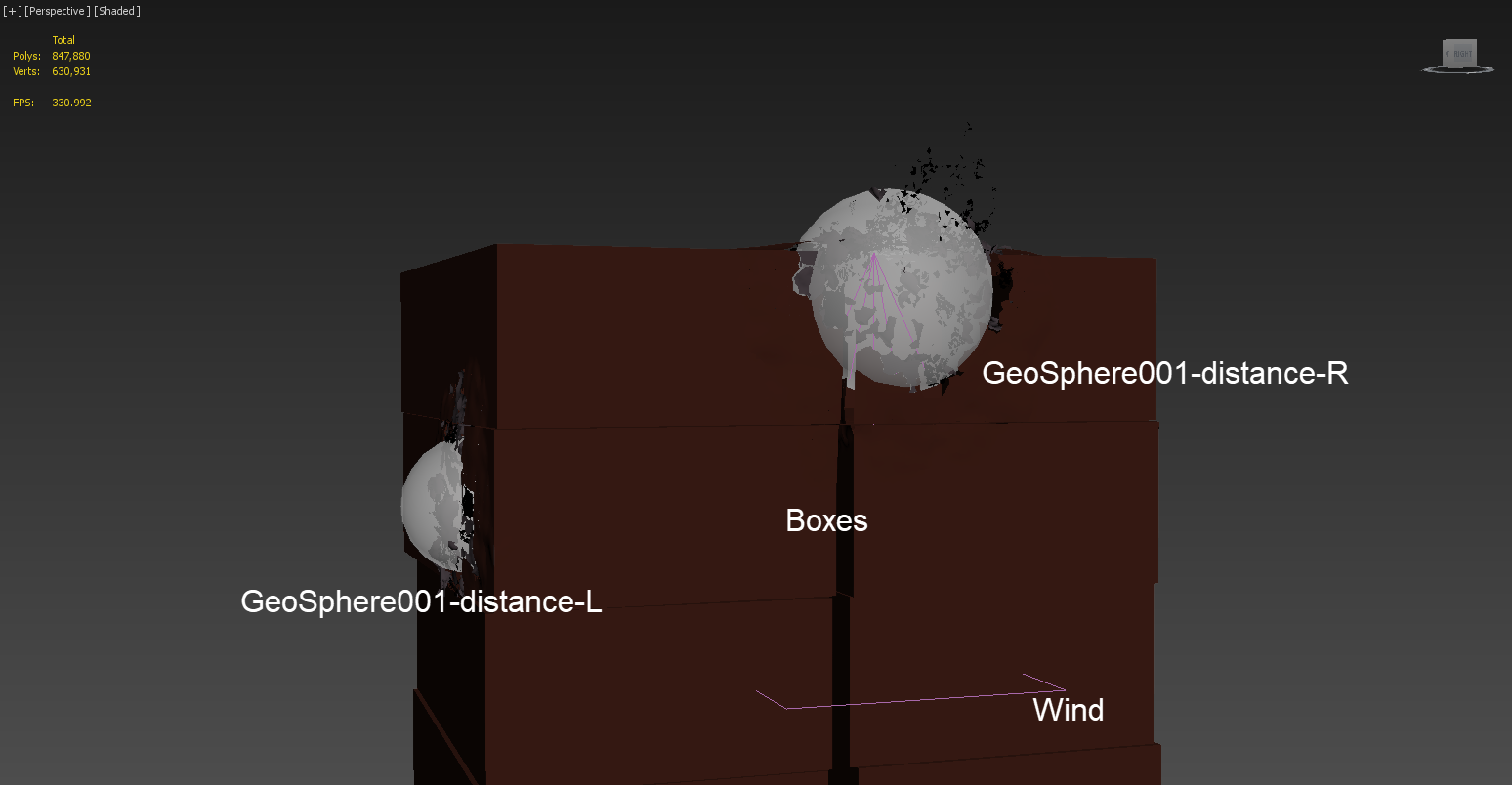
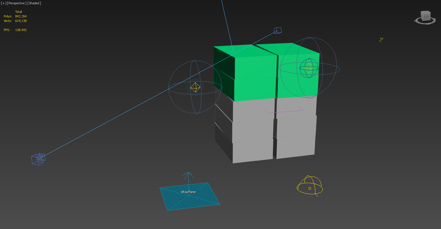
This picture shows the final scene close-up. There are two animated GeoSpheres (shown in See-Through mode) used for distorting the burning boxes (through V-Ray Displacement in its shader). We have animated the position and size of the two spheres, matching the growth of the burning area. In later steps, we add those two geosphere geometries in the VRayDistance texture, and use that texture in the displacement slot for the box shader.
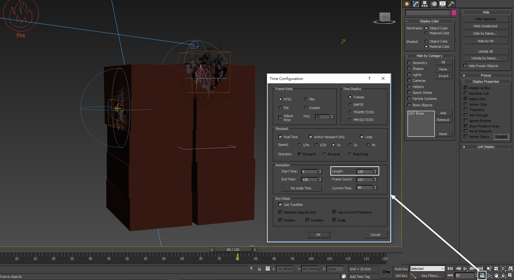
Set the Time Configuration → Animation Length to 120 so that the Timeline goes from 0 to 120.
The final simulation is 120 frames long. While setting up the Simulator's dynamics and the Fire/ Smoke Source, you can set Animation Length to 75 frames or even shorter, to iterate faster.
Boxes Geometry Preparation
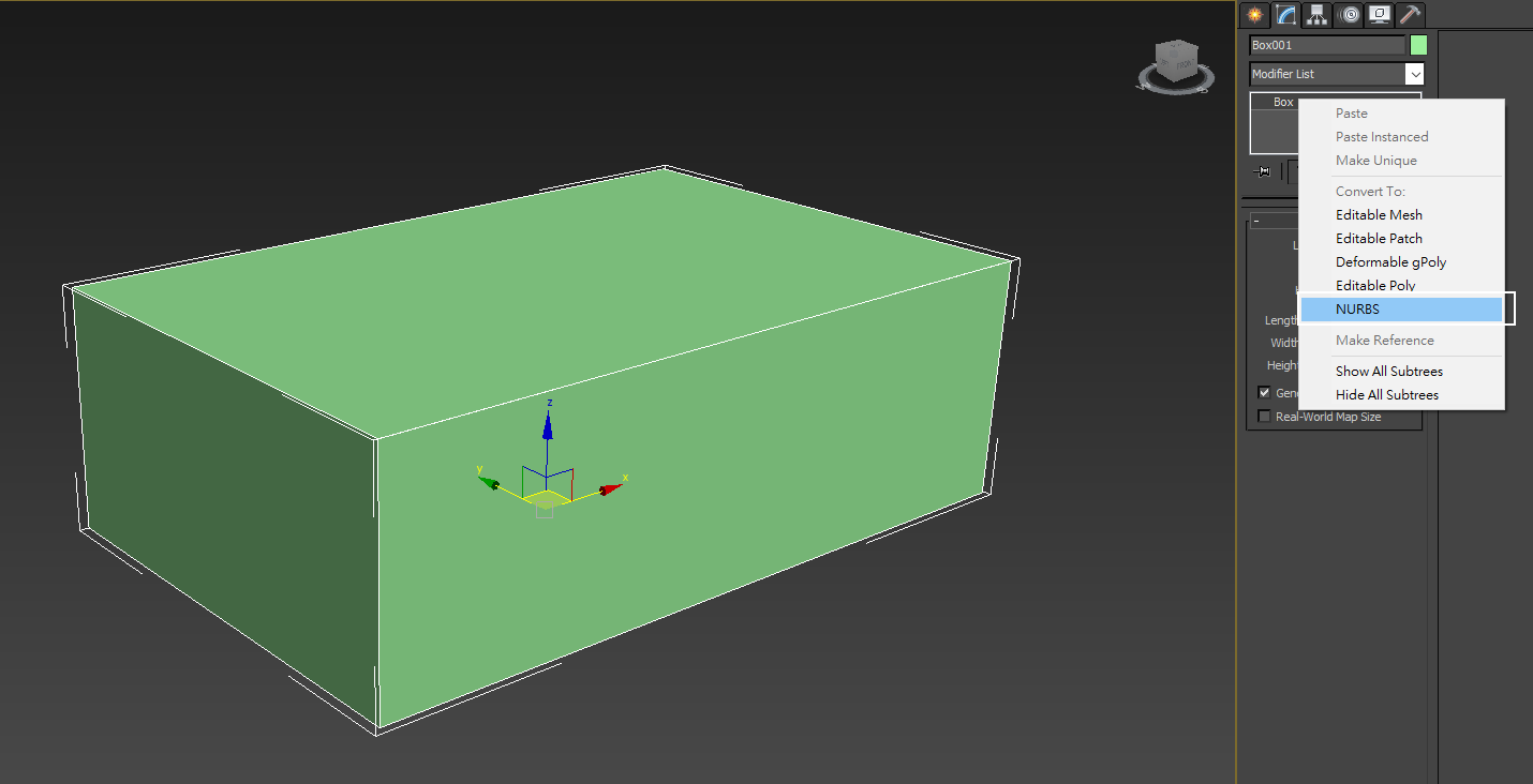
When the cardboard burns, the paper disintegrates into ashes during the burning process. Therefore we need enough details in the geometry for making realistic ashes. We start with very simple box geometry, a box without any segments. Size is 70 X 111 X 37 cm. Then, we convert it into NURBS.
Since you can find this box geometry in the downloadable scene file, you can skip those steps and start from "Burning_Boxes_max2015_Start.max", and focus on the Phoenix setup.
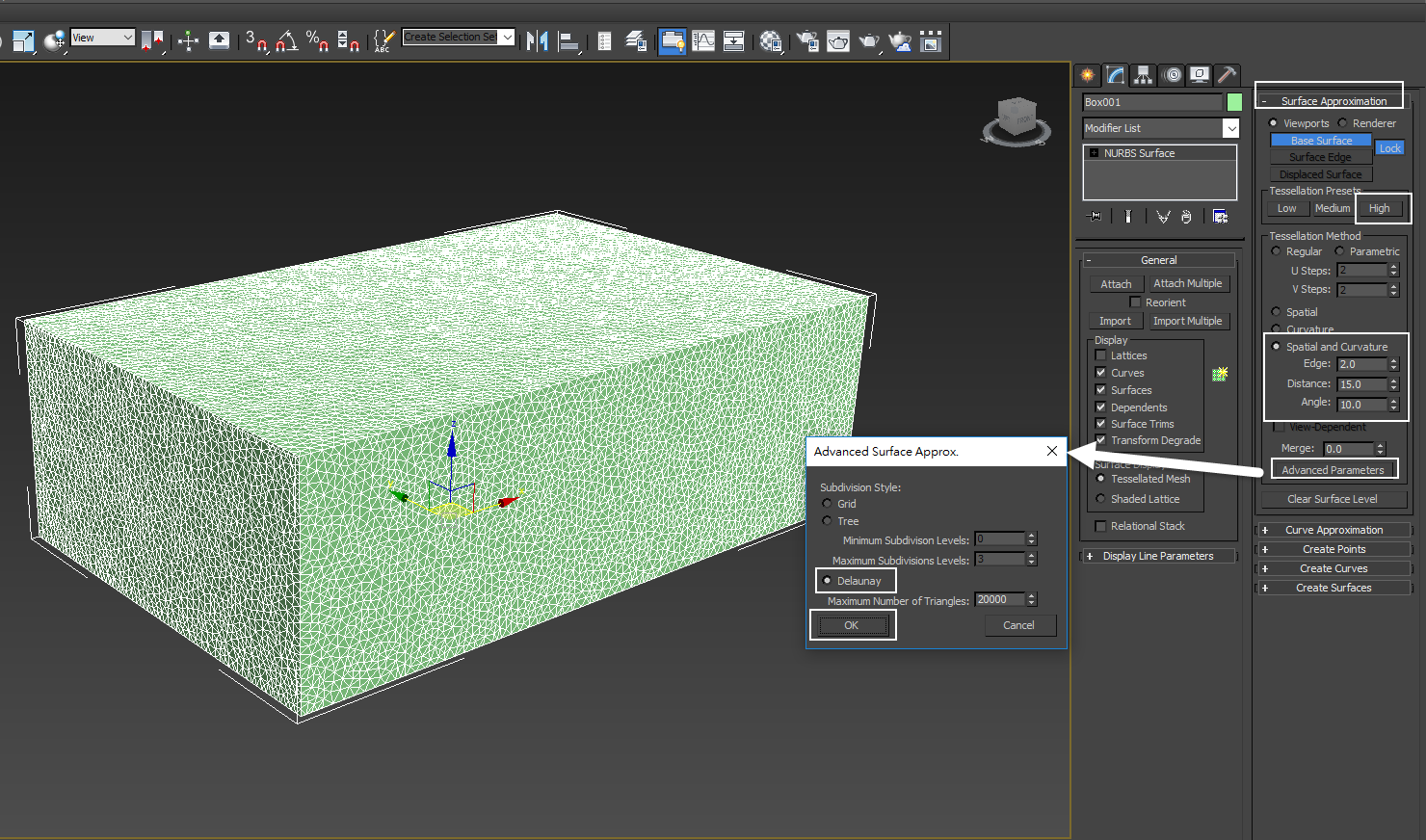
With the NURBS box selected, go to the Modifier panel, in the Surface Approximation rollout and set the Edge to 2.0. Then click on Advanced Parameters and enable the Delaunay option. This creates random edges over the surface of the box. The Delaunay triangulation topology is also suitable for cloth or softbody type of simulation. For the flying paper pieces, we are going to simulate the softbody with BulletPhysics in thinkingParticles.
Convert the NURBS to Editable Poly geometry.
With the editable poly mesh selected, go to the Modifier panel, randomly select a small patch of the faces and detach them. Repeat the process until all faces are detached into small patches.
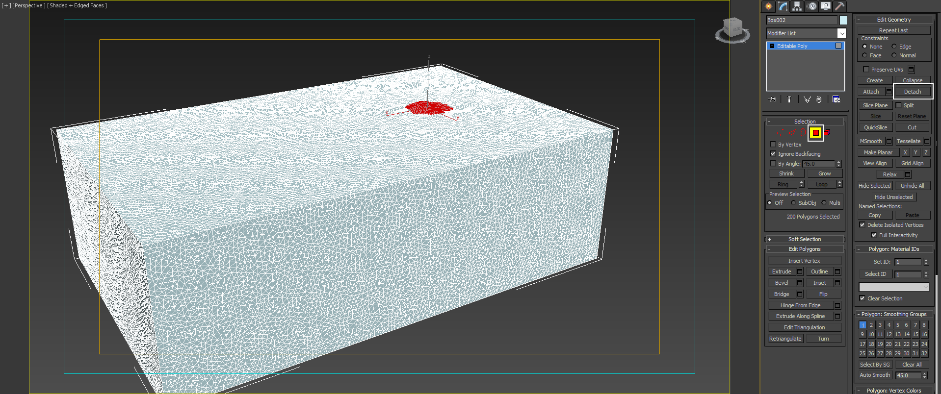
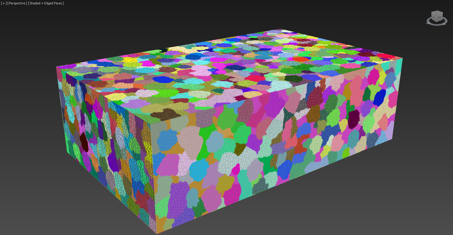
Check the screenshot showing the mesh in the viewport. We have assigned a different color to each patch for demonstration purposes. Once you have those small patches ready, attach all of them back to one single box geometry. Through this editing process, we create a box with irregular edges on its surface. This is good for the disintegrating effect we are trying to achieve with thinkingParticles.
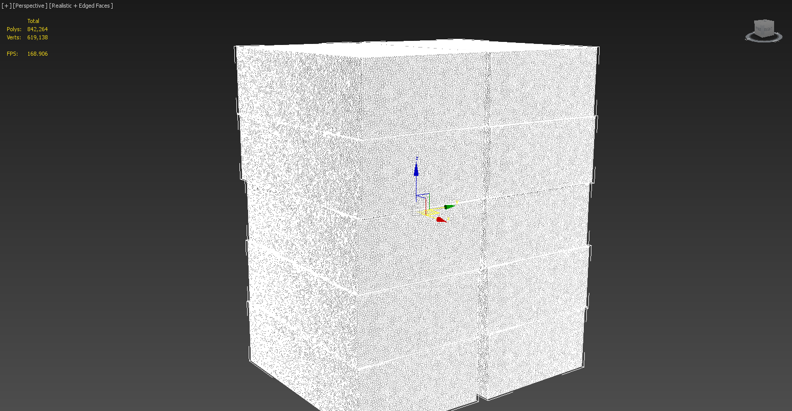
Duplicate the box that we have created in the previous step few times, and pile them up as the image shows. In this example, we made ten copies. Rename them to Box001 ~ Box010.
thinkingParticles Dynamic Sets
As this tutorial is about thinkingParticles working with Phoenix, the focus is not on how the dynamic sets were done. However, below is an outline of some critical dynamic sets.
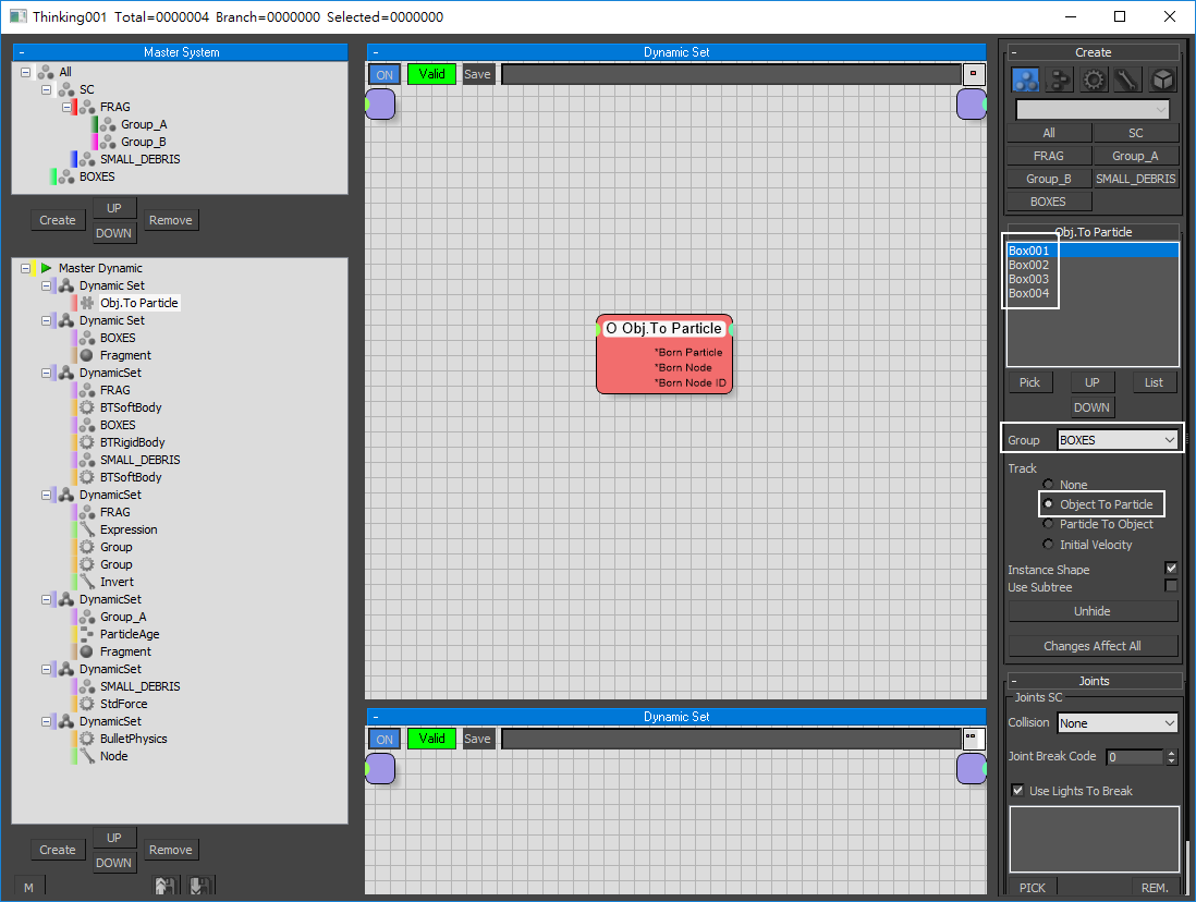
Four box geometries (Box001 ~ 004) are taken into thinkingParticles through Obj. To Particle operator. Then those boxes are hidden in the scene.
The boxes then are activated by two omni lights (Omni001 and Omni002) in the scene (through fragment operator). The omni lights are animated to control part of the boxes to start burning.
The activated fragments then divide into two groups: Group A and Group B.
Then the paper fragment - Group A breaks into smaller debris called SMALL_DEBRIS.
Then the smaller debris is subjected to the Wind force in the scene. The turbulence from the Wind pushes the smaller debris and gives them some random motion.
We only include four boxes (the top four boxes) in the scene instead of all ten. This is because we want to save time for caching particles. With all boxes in the scene, the thinkingParticles caching process will take longer to complete.
The Far Attenuation of the omni lights controls how far the box starts disintegrating. You can adjust the position of the lights or change their far attenuation to customize the effect. This is a standard practice, and that thinkingParticles will automatically read the attenuation of the lights and use it.
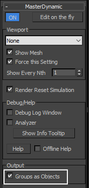
On the right side of thinkingParticles UI, under MasterDynamic rollout, we check the option Groups as Objects. This option turns every particle group into geometry. We put those geometries in a VRayDistance texture modulating fire opacity.
Enabling the Groups as Objects option generates many geometries from the particle groups and blocks the Phoenix fluid simulation. Be sure to put those extra objects in the Scene Interaction - exclude list of your Phoenix Simulator with the later steps.
Cache the thinkingParticles
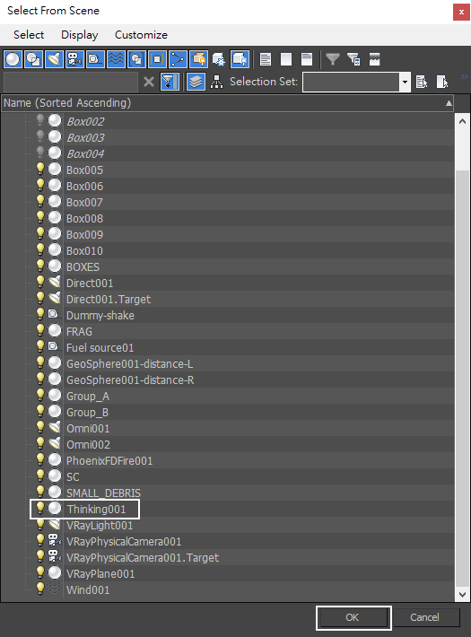
There is a multitude of small fragments in the scene, that would slow down the viewport dramatically. So, before we run any simulation, it's better to cache the particles. Go to Select by Name and select the thinkingParticles node (Thinking001 in this case).
Don't move the time slider until you cache the particles. It will take a long time for thinkingParticles to update the viewport. Keep the time slider at frame 0.
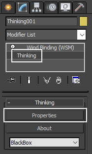
With the thinkingParticles node (Thinking001) selected, go to Modifier Panel and press the Properties button.
Note that the thinkingParticles node is bound to the Wind spacewrap in the scene. The wind force gives the Small_Debris particles some random movement.
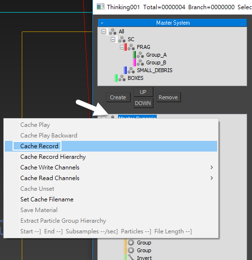
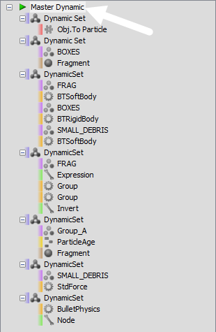
Right-click on Master Dynamics and select Cache Record.
Make sure the boxes that are taken into the Obj. To Particle operator do not have any material applied. In the shader session, we are going to use a VRay material with Displacement. When caching record with thinkingParticles, tP will actually cache VRay Displacement into the cache sequence, which will make the caching process much slower.
Make sure the two omni lights are turned on before you start the cache record process. Without those two lights, thinkingParticles won't initiate the activation for converting boxes to smaller fragments.
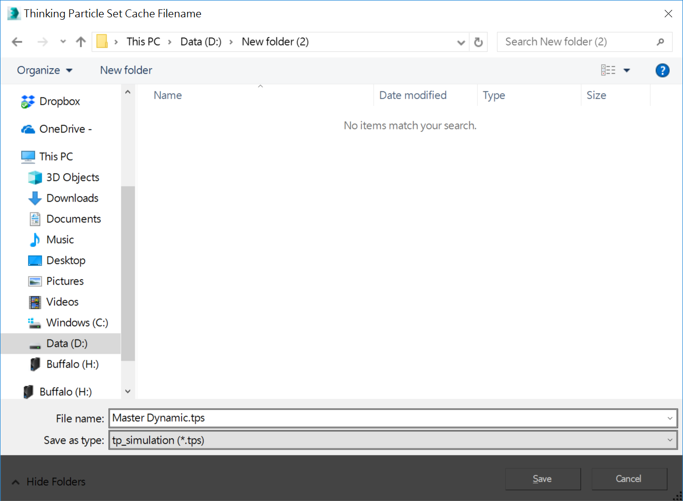
A prompt dialog appears for saving the cache. We save the cache in a *.tps file format.
After cache generation is finished, a green arrow appears on the left of Master Dynamic.
Now you are free to move the time slider. The viewport can update much swifter.
In this example, the Boxes object is shown in green color; Group_B object is shown in magenta; SMALL_DEBRIS object is shown in blue color.
Once thinkingParticles cache process has completed, turn off Omni001 and Omni002 lights in the scene, as their function was purely for particle activation inside thinkingParticles, not for lighting purposes in the scene.
Again, the steps below explain how to create a light, a camera, a vrayplane in the scene and preparation of the pre-fragmented box geometries. All of those are already set up in the downloadable scene file, hence, you can skip those steps and start from "Burning_Boxes_max2015_Start.max", and focus on the Phoenix setup.
Lighting
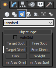
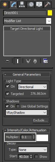
Go to Create Panel → Lights → Standard and press the Target Direct button. Click and drag to create a Direct Light in the scene.
Move the Direct Light until you get the lighting condition you like. The exact transformation values for this example are:
Direct Light XYZ: [ 44cm, -146cm, 336cm ]
Direct Light Target XYZ: [ -26cm, -42cm, -20cm ]
With the Direct light (Direct001) selected, go to the Modifier panel and decrease the Multiplier to a value of 0.1.
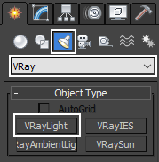
Go to Create Panel → Lights → VRay and press the VRayLight button. Click and drag to create a VRay Light and place it anywhere in the scene.
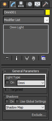
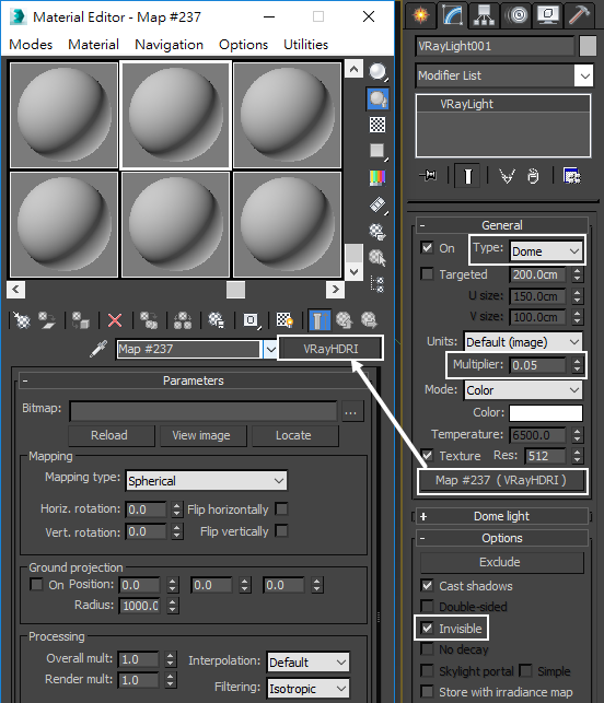
With VRayLight selected, go to the Modifier panel. Set type to Dome.
Decrease the Multiplier to a value of 0.1.
In the Options rollout, check the Invisible option.
You can put a VRayHDRI texture in the Dome Map slot. Feel free to use an HDRI map of your choice. Decrease the Multiplier to a value of 0.05.
Camera
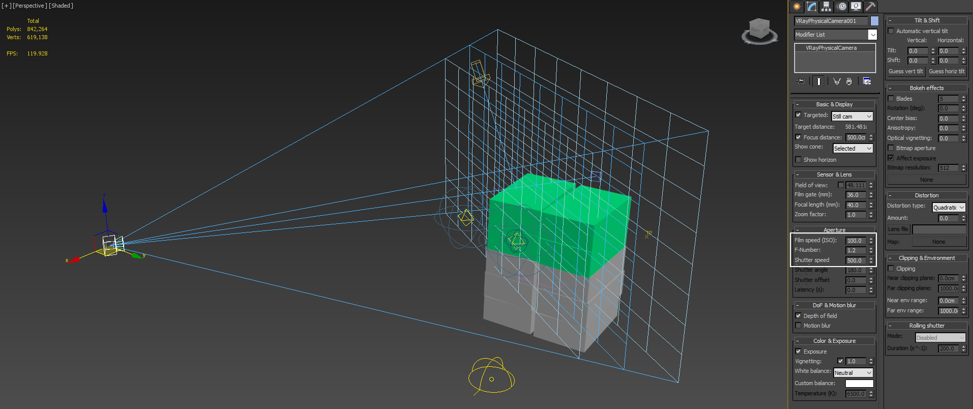
Go to Create Panel → Camera → VRay, click on the VRayPhysicalCam button, and then create a VRayCam in the scene.
The exact transformation values for the camera are:
Camera XYZ: [ 438cm, -357cm, 183cm ]
Camera Target XYZ: [ -27cm, -9cm, 197cm ]
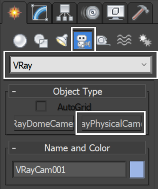
The Physical camera is set to F-Number: 1.2, Shutter Speed: 500, ISO: 100. In the sample scene the camera is animated for a more interesting camera composition.
Focal Length is 40 mm.
V-Ray Plane
Go to Create Panel → Geometry → VRay and press the VRayPlane button. Create a VRayPlane in the scene. The V-Ray plane is used just for rendering and does not affect the simulation.
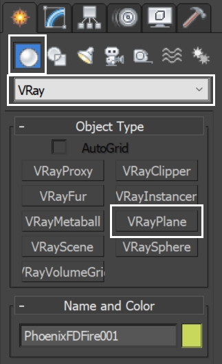
Place the VRayPlane anywhere in the scene.
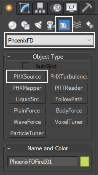
Fire/Smoke Source
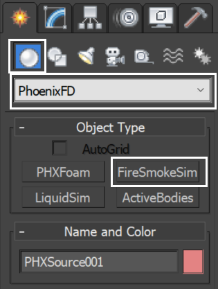
Go to Create Panel → Helper → PhoenixFD and press the PHXSource and create a Fire/Smoke Source (PHXSource001) in the scene.
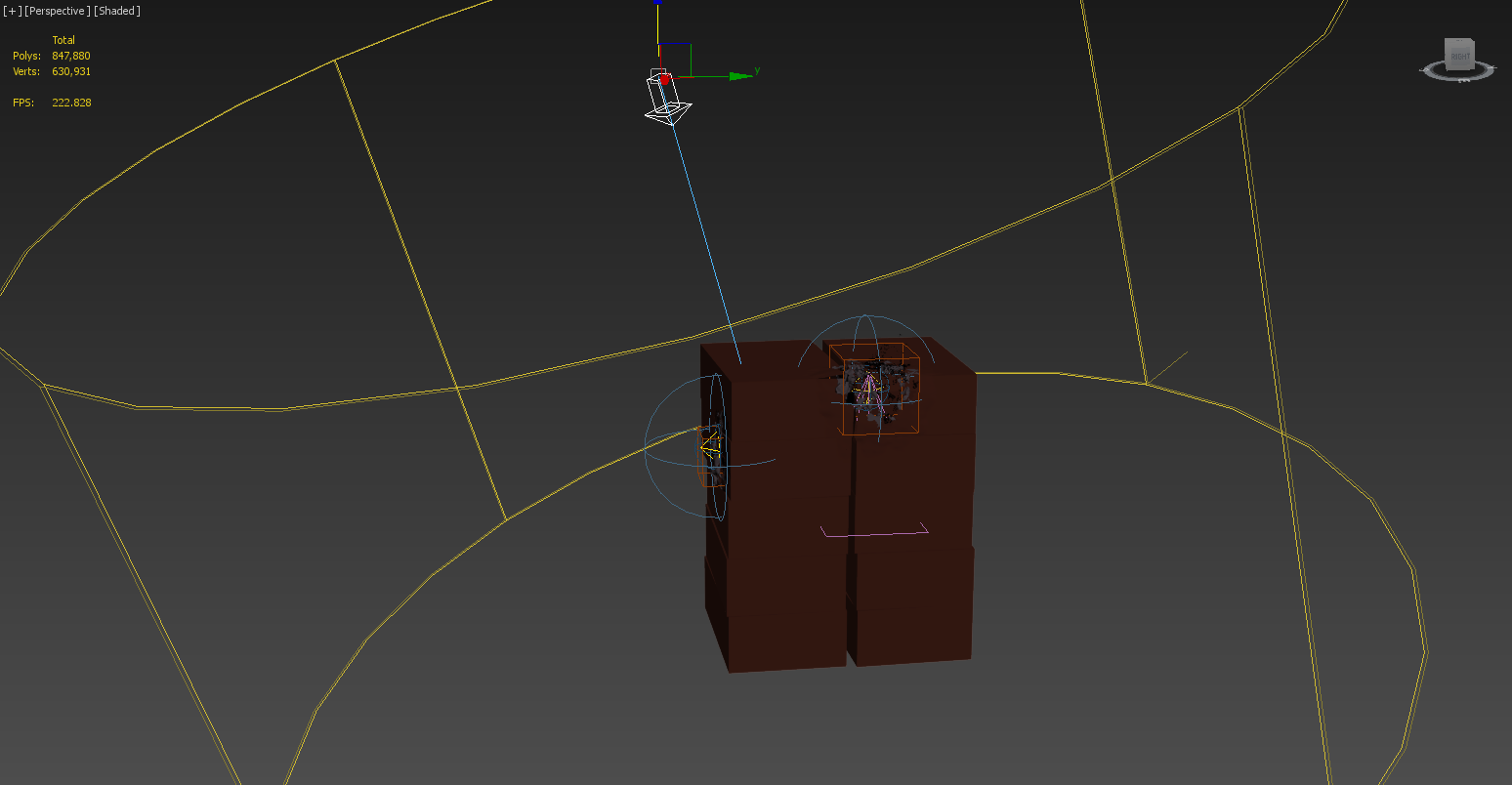
With PHXSource001 selected in the Modifier panel, press the Add button in the PHXSource and select thinkingParticles node (Thinking001, pointed by the white arrow) in the scene.
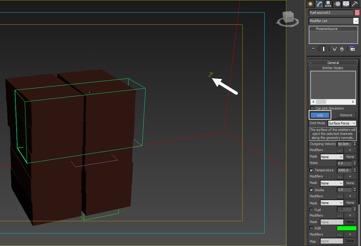
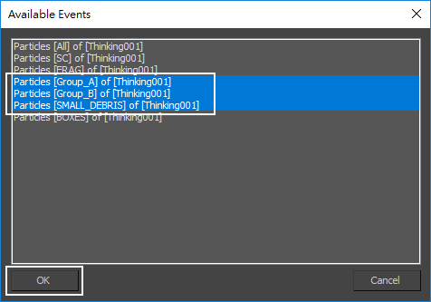
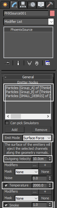
Phoenix automatically generates a list of particle sets in your scene. Pick up the Particles Group_A, Group_B and SMALL_DEBRIS of Thinking001 and press OK. Those are the particle groups we want to emit fluid.
Set the Emit Mode to Surface Force, and leave the Outgoing Velocity, Temperature and Smoke amount at their default value.
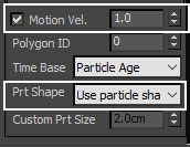
At the bottom of PHXSource, Prt Shape is set to Use Particle shape. This means Phoenix can read shape data from thinkingParticles.
Simulation Grid
Go to Create Panel → PhoenixFD, press the FireSmokeSim button, and then click and drag a Fire/Smoke Simulator into the scene.
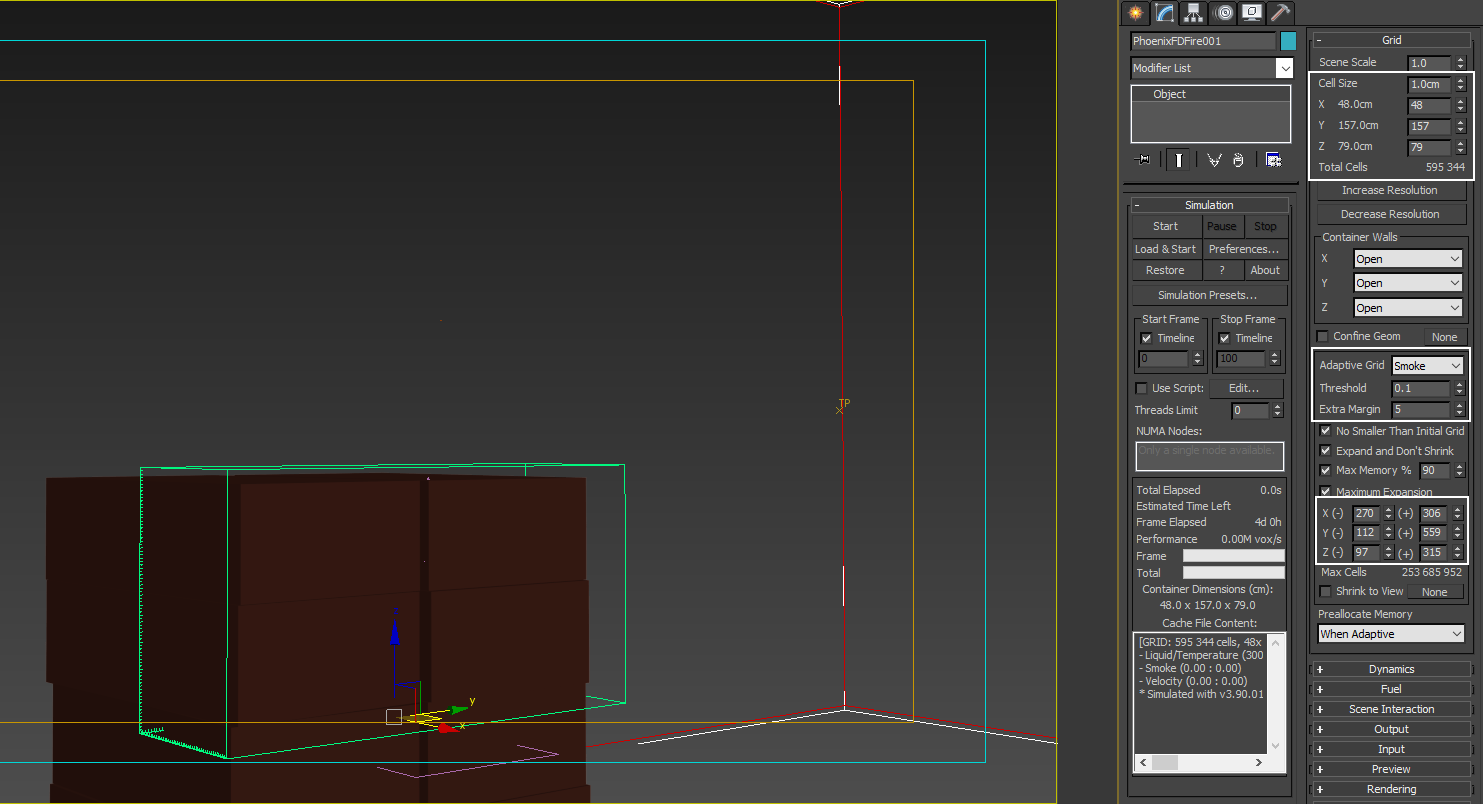
Set the volume of the Grid as shown in the example. The grid is shown in purple color. Set its x, y, z respectively to 48, 157, 79, the Scene Scale to 1.0, and Cell size to 1.0 cm. Enable Adaptive Grid (based on Smoke) and set Extra Margin to 5, so the grid would be able to expand and accommodate the growing smoke. Also, enable the Maximum Expansion option and set the values as shown (parameters are circled in white, in the viewport the grid is in red color). Adaptive Grid allows you to save memory and simulation time as the simulation grid is not set to its largest extents at the very beginning and expands gradually.
The exact position of the Simulator in the scene is [ 44, -41, 96 ].
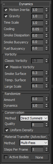
Leave all parameters in the Dynamics rollout to their defaults.
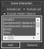
In the Scene Interaction rollout, add BOXES, FRAG, GeoSphere001-distance-L, GeoSphere001-distance-R, Group_A, Group_B, SC, SMALL_DEBRIS and Wind001. That way they won't affect or block the fluid simulation.
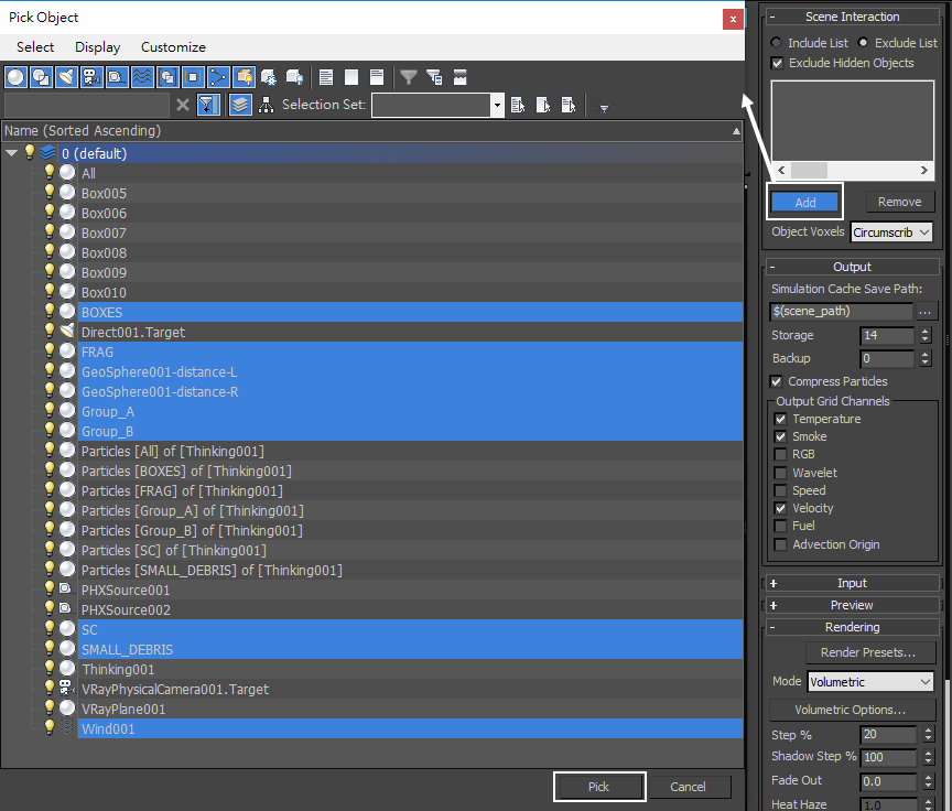
These geometries and force are now added to the Exclude List.
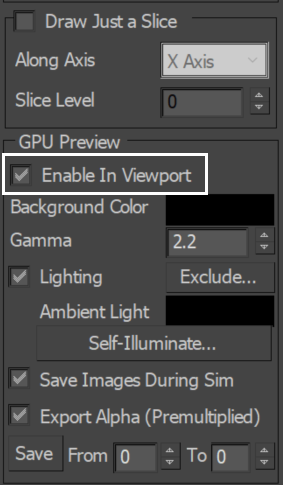
In the Preview rollout, enable the GPU Preivew option, so that we can preview the smoke shading directly into the viewport.
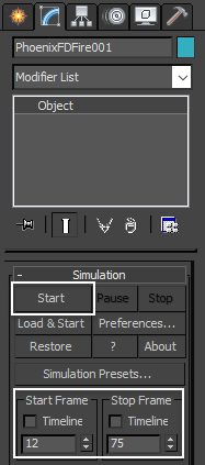
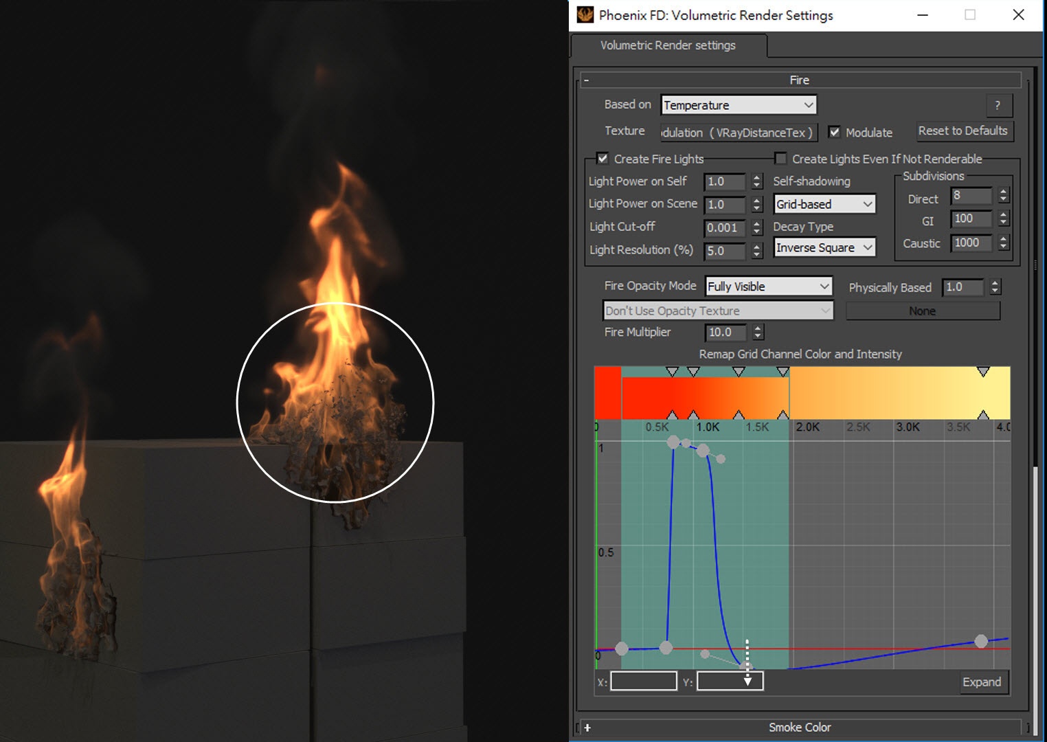
Because the disintegration of the boxes won't start until frame 12, disable the Start Frame and Stop Frame Timeline and set it to 12 and 75 respectively. This should save some simulation time. Press the Start button to start the simulation.
Though the total animation is 120 frames, we only simulate until frame 75 to have faster iterations.
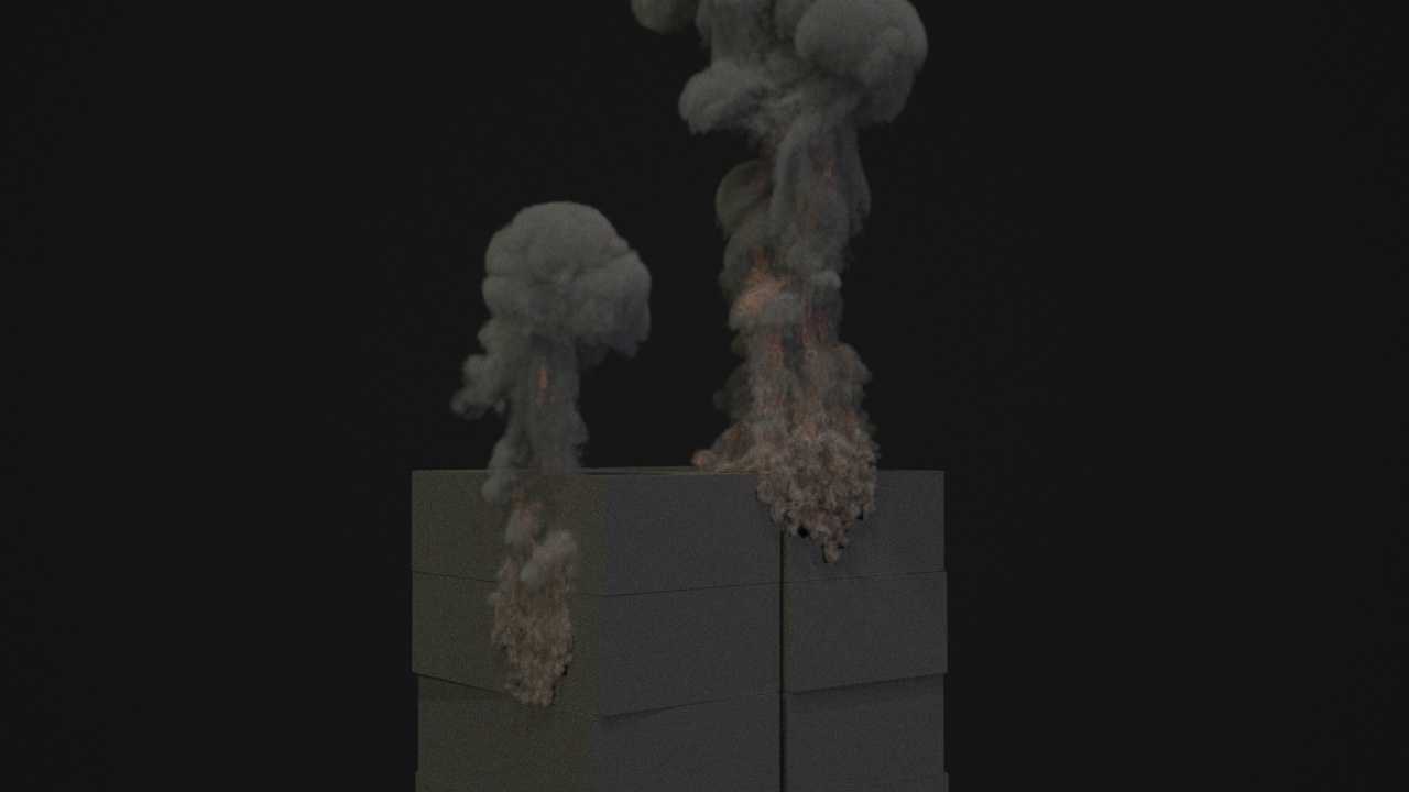
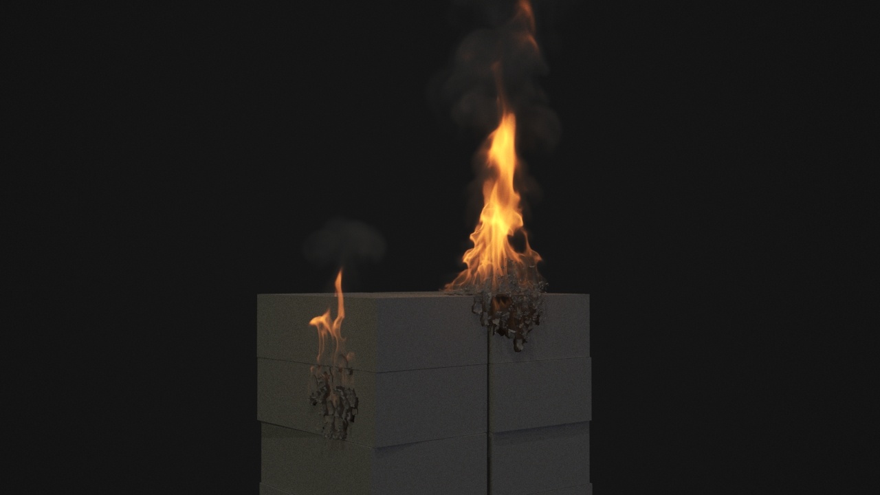
Once the simulation is completed, you can make a preview animation. These are our first results. As you can see, there is not much detail in the fire, and the smoke seems too thick. Let's see how to correct it.
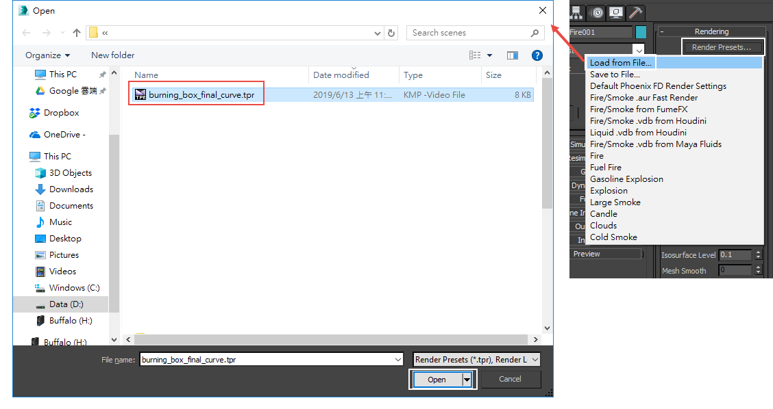
Go to the Fire/Smoke Simulator → Rendering rollout, click on Volumetric Options. Adjust the curve like shown in the image.
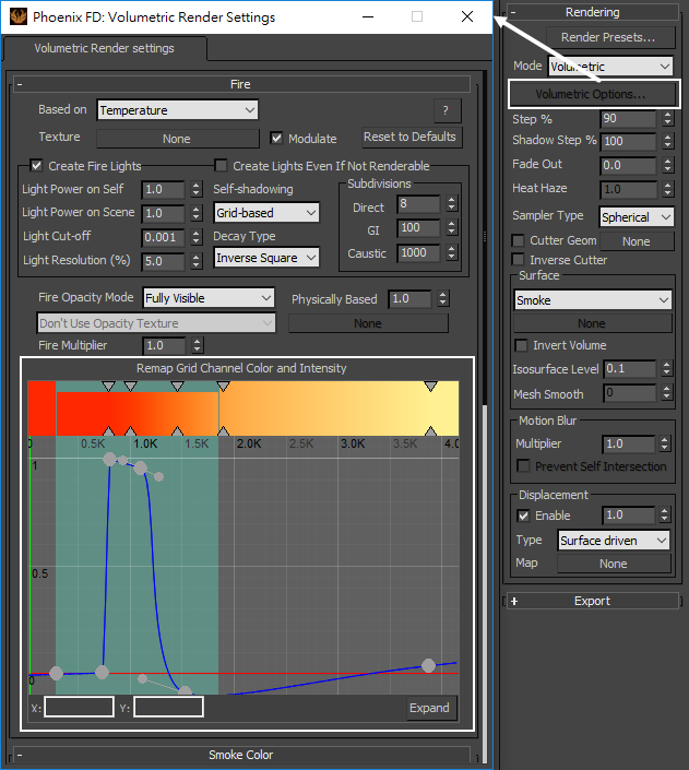
Or you can simply load up a Rendering Preset from a *. tpr file that is provided in the sample scene.
Render an image. The smoke seems too thick, so the fire should be brighter.
If following along using the provided project files, please make sure the two Omni lights (Omni0001 and Omni0002) used for the thinkingParticles simulation are disabled so they are not contributing to the scene lighting.
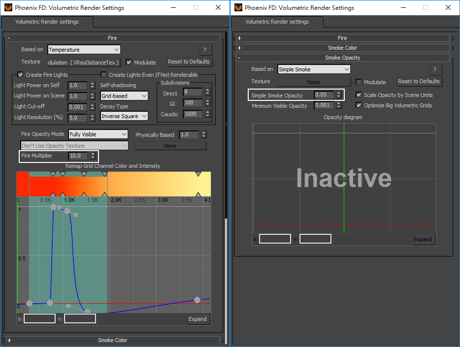
Increase Fire Multiplier to 10.0. Reduce Simple Smoke Opacity to 0.05.
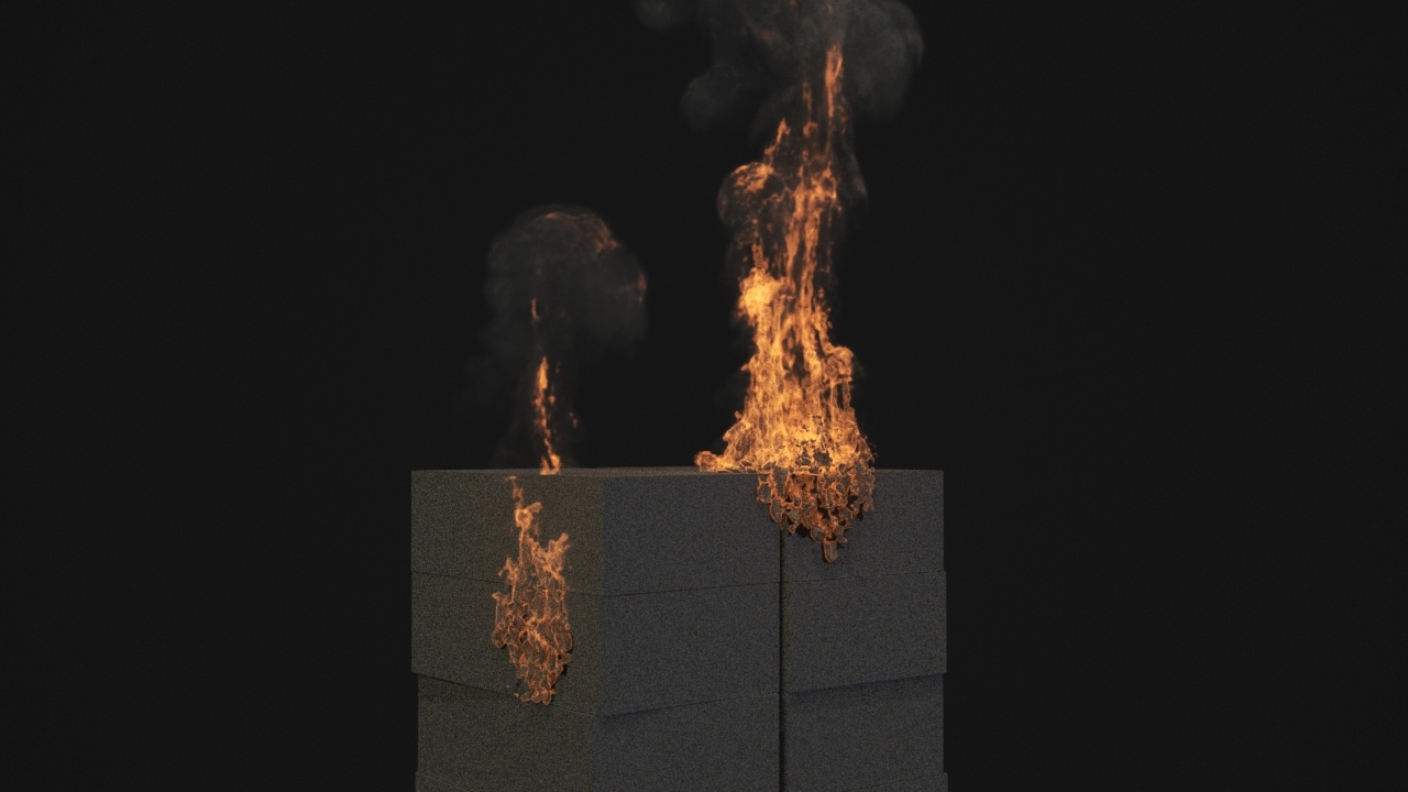
Render again. Now the fire looks brighter, and the amount of smoke is adequate.
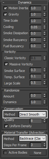
Change the Conservation Method to Direct Smooth; Material Transfer to Backtrace; Steps Per Frame to 3. With those settings, you will have a better looking small scale fire.
Create a preview animation. With higher Steps Per Frame, we have smoother fire. And Direct Smooth conservation method gives us better looking fire.
For aesthetics purposes, we want our fire animation slower. Let's decrease Time Scale of Fire/Smoke Simulator to a value of 0.7.
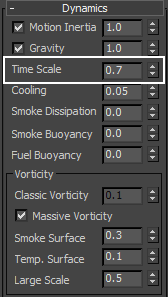
Simulate again. As you can see, with Time Scale set to 0.7, the fire became slower.
Make a test rendering. Now the fire appears unrealistic, because at its root it is too solid. Let's address that.
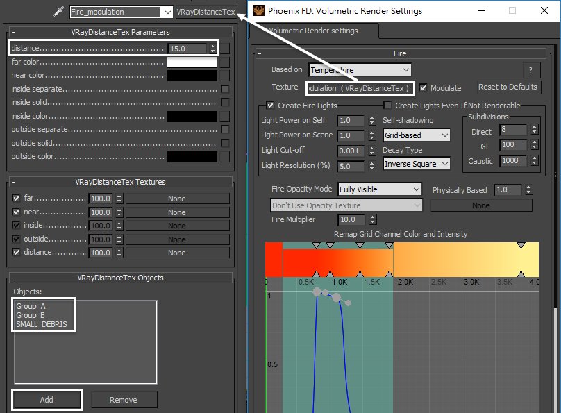
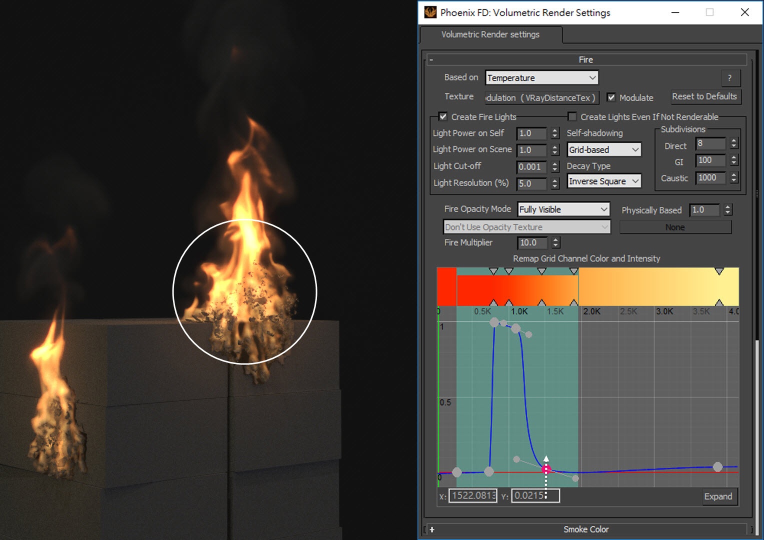
Go to Fire/Smoke Simulator → Rendering rollout, Volumetric Option. In the Fire rollout, put a VRayDistanceTex in the Texture slot. Enable the Modulate option. In the VRayDistanceTex, add Group_A, Group_B and SMALL_DEBRIS in the list.
The VRayDistanceTex is a V-Ray specific procedural texture that returns a different color based on a point's distance from an object(s) specified in a selection list. We can use this texture as a mask to modulate the fire opacity.
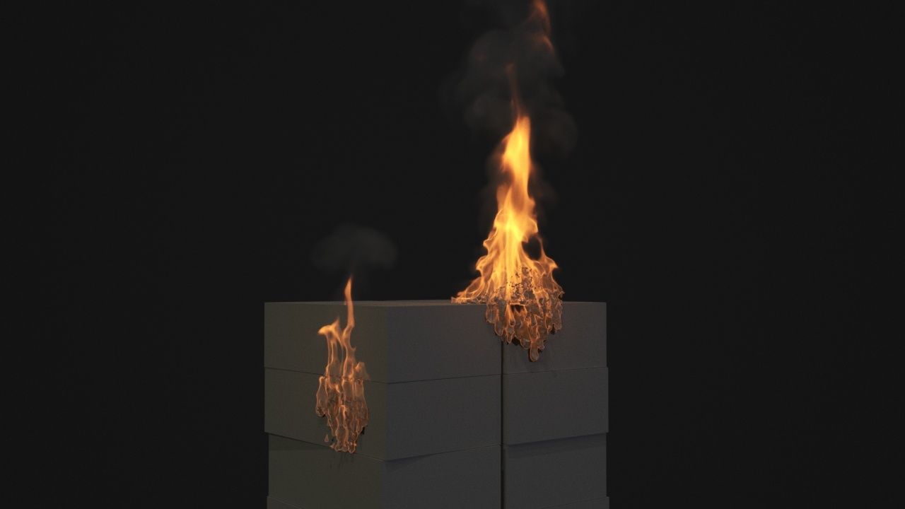
Make a test render now with VRayDistance in the modulate slot. The fire looks more realistic.
If your fire looks not so good even if you already loaded up the provided *. tpr file, you can try moving the control point on the curve up or down. Notice how the position of that point affects the core strength of the fire. When the point is in the upper position, the core looks more solid and brighter, while in the lower position, it looks weaker at the core. Fine-tune the control point to get the best appearance of the fire.
Now that the simulation looks good, check the Stop Frame Timeline option so that it simulates from frame 12 to 120. Press the Start button to the simulation of the whole animation.
Once the simulation is completed, let's make a preview animation. The result appears acceptable in the preview. Then we run a test rendering to see if everything looks good.
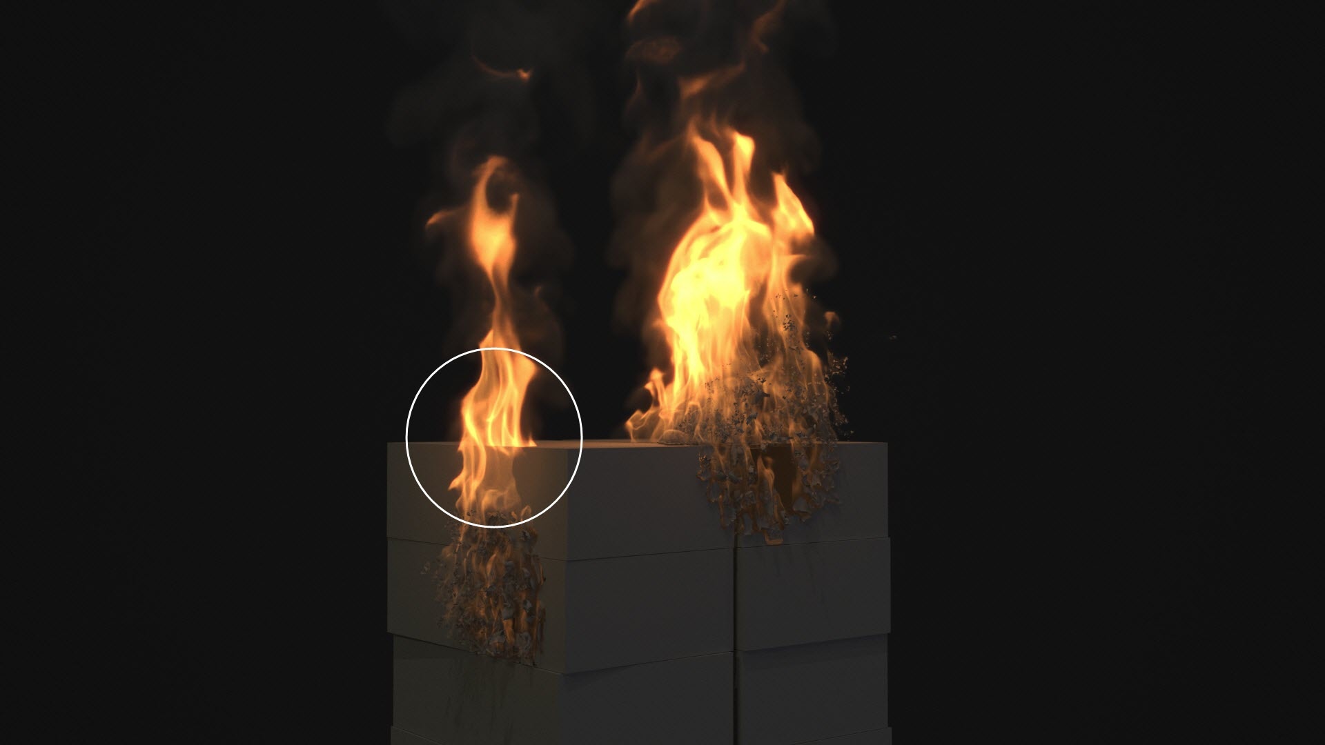
As you can see in the test rendering, the fire on the left is penetrating the boxes. We have to fix this clipping issue. This happens because all the Phoenix generated thinkingParticles' groups are non-solid by default. We have to check the solid option in their Phoenix Per-Node Properties manually.
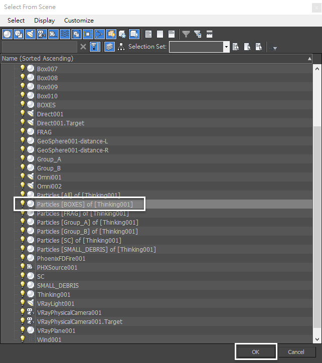
Go to Select by Name, select the Particles BOXES of Thinking001 in the list.
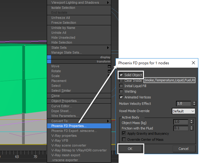
With the Particles BOXES of Thinking001 selected, right-click and choose Chaos Phoenix Properties. Check the Solid Object option. This option can assure that the fluid collides with BOXES group instead of penetrating them.
Here we only enable the Particles BOXES of Thinking001 solid option. If you enable solid to all the Phoenix generated thinkingParticles particle groups (including FRAG, Group_A, Group_B, SC and SMALL_DEBRIS of Thinking001), then you won't see any fire generated from Fire/Smoke source, as those particle groups block the fluid.
Run the simulation again. Make a preview animation. As you can see, the solid boxes diminish the strength of the fire, especially the initial phase of the burning fire.
To compensate for the problem, we increase the value of Outgoing Velocity of the PHXSource to a value of 200.0.

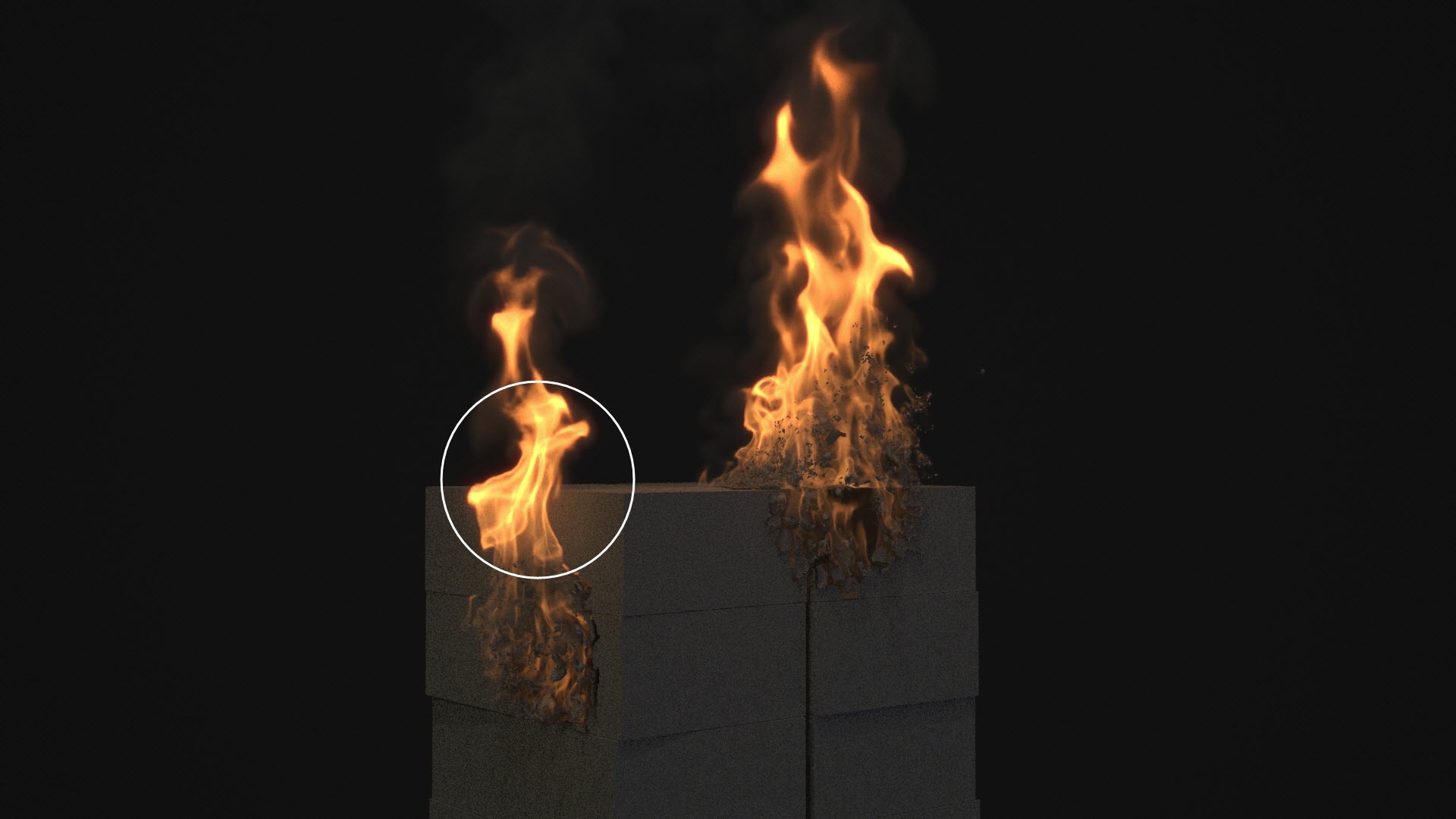
Run the simulation again. Make a preview animation. Now the fire regains its strength to some degree and looks better.
Also there is no clipping issue between the fire and the boxes. So we are all set for the fluid simulation, ready to enter the next stage.
Materials
Here is a short material overview: we are going to create three different materials - (A) Box Material, (B)Burning Paper Material, (C)Burned Paper.
(A)Box Material
The box material is basically two materials mixed together: (1)Burned Box material and (2)Unburned Box material. The blending mask is a VRayDistanceTex that uses two geospheres to generate black and white mask texture. On top of the V-Ray Blend Material, we add V-Ray Bump Material to give the boxes round-edge look during render time.
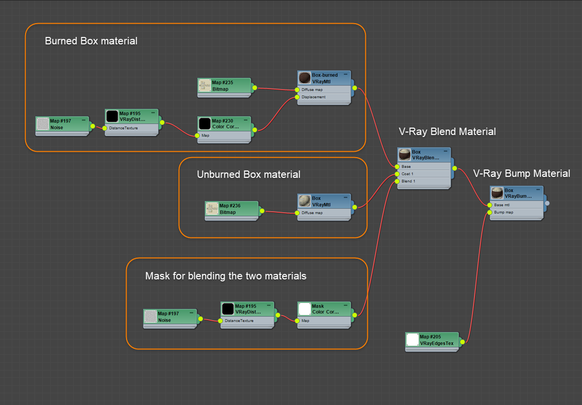
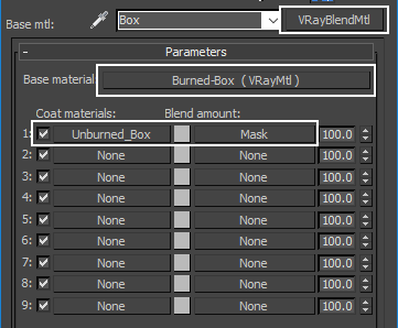
Let's start with a VRayBlendMtl connected to the Base material and then in the first Coat material slot plug in a VRay Material. Rename them to Burned-Box and Unburned_Box respectively.
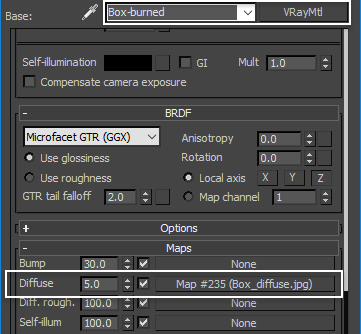
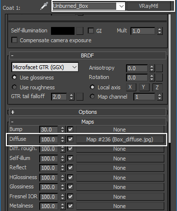
For the Burned-Box material, put Box_diffuse.jpg in the Diffuse slot. Set the Diffuse Color to RGB of (11, 2, 1).
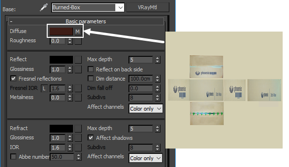
For the Burned-Box material, reduce the diffuse value from 100.0 to 5.0. The combination of bitmap and diffuse color makes the texture darker, as it was burned.
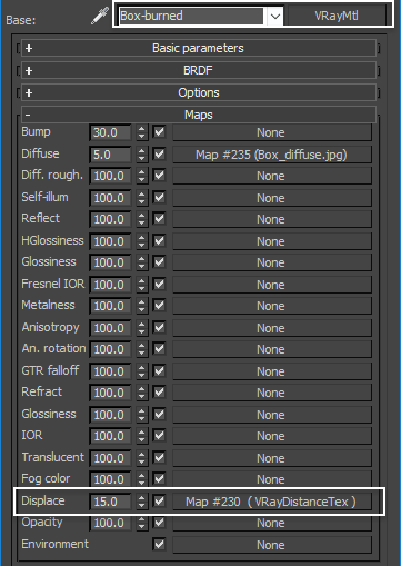
For the Burned-Box material, plug in a VRayDistanceTex in the Displace slot. Set the Displacement value to 15.0.
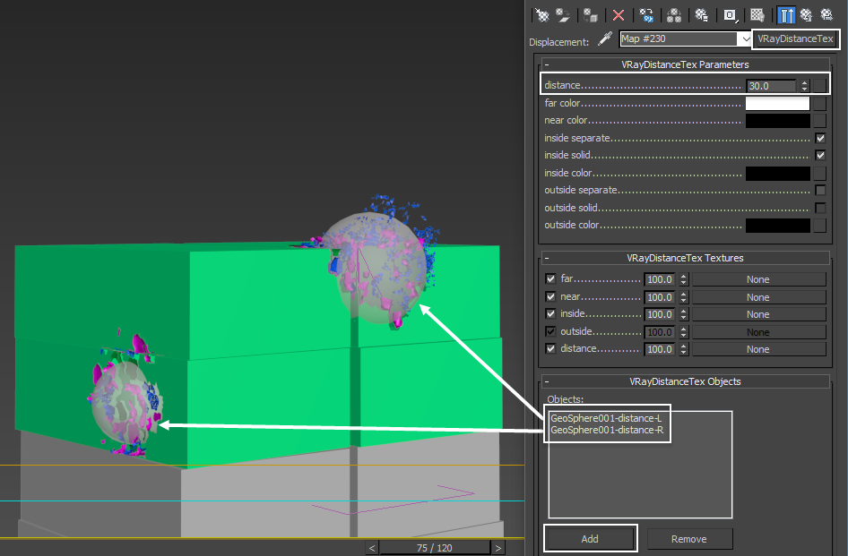
For the VRayDistanceTex Objects add in the two GeoSpheres in the scene. Set the distance to 30.0.
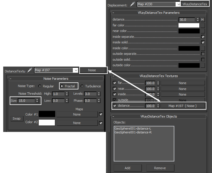
For the VRayDistanceTex, put a Noise texture in the distance slot, to randomize the distance. By doing so, we will have a more organic looking mask. For Noise texture, set the type to Fractal. Size set to 15.0.
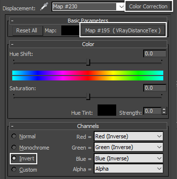
To invert the VRayDistanceTex, we add a Color Correction on top of that. Set its channel to Invert.
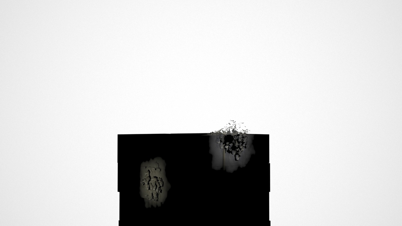
At this point, if we apply the texture map to the Diffuse Color of a default V-Ray Material, we should get something like the image on the right. This texture is ready for Burned Box displacement map.
The Unburned_Box material is very straightforward. Simply put the Box_diffuse.jpg in the Diffuse slot.
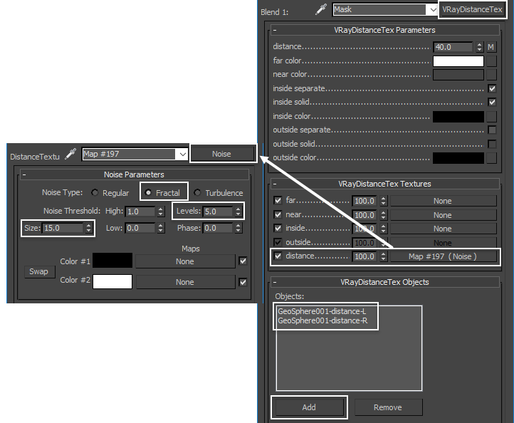
For the mask, we are blending the Burned and Unburned materials, using a VRayDistanceTex. In the texture, add two GeoSpheres in the VRayDistanceTex Objects list. Add a Noise texture in the distance slot. Set the Noise Type to Fractal, Size to 15.0, Levels to 5.0.
The two GeoSpheres are keyframed for their size and position to match the growing burning area of the boxes. You can adjust the GeoSpheres position and size based on your need in order to customize the burning appearance.
Now let's apply this material to the BOXES (an object generated by checking Group ad Object in thinkingParticles) and Box005 ~ Box010. The rendering results are as on the image shown. But the edge of the boxes is too sharp and unrealistic.
On top of VRayBlendMtl (Burned and Unburned materials) add a VRayBumpMtl. Set the Bump amount to 100.0. In the bump map slot, plug in a VRayEdgesTex. Set the Radius to 0.5cm.
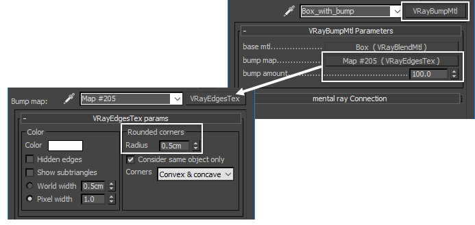
The image shows the rendering with V-Ray Bump material applied. Notice the subtle rounded edge in the boxes.

(B)Burning Paper Material
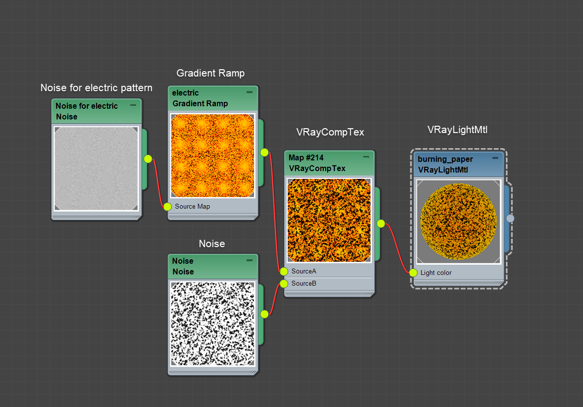
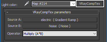
This image displays an overview of the complete Burning Paper Material. Because the burning paper emits light, we choose VRayLightMtl to start with. Then we put in a procedural texture in the Light color.
Start with VRayLightMtl and rename it to burning_paper. Set the Color to 0.2.
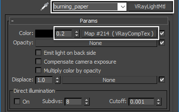
In the VRayCompTex, put a Gradient Ramp in Source A. Put a Noise texture in Source B. Set Operator to Multiply (A*B).
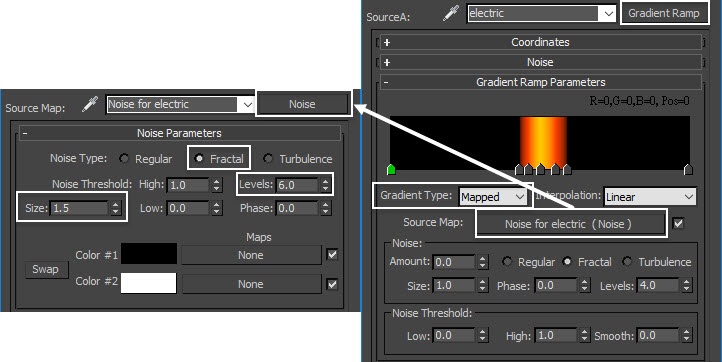
For the Gradient Ramp set the Gradient Type to Mapped. Put another Noise texture in the Source Map. Change the gradient like shown on the image, with dark orange color RGB (255, 12, 0), yellow color RGB (255, 155, 0). Set the Noise Type to Fractal, Size to 1.5, Levels to 6.0.
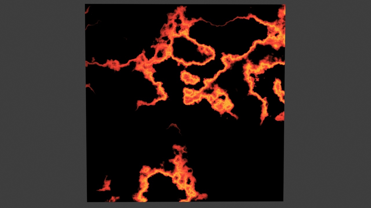
To show you what this complete VRayLightMtl looks like, we applied the material to a simple plane. It is an orange-yellow electric pattern. When the material is ready, apply it to the SMALL_DEBRIS.
(C)Burned Paper Material
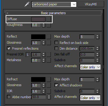
For the burnt paper (carbonized paper), we use VRay Material and set the Diffuse color to RGB (16,12,14). We apply this material to Group_B.
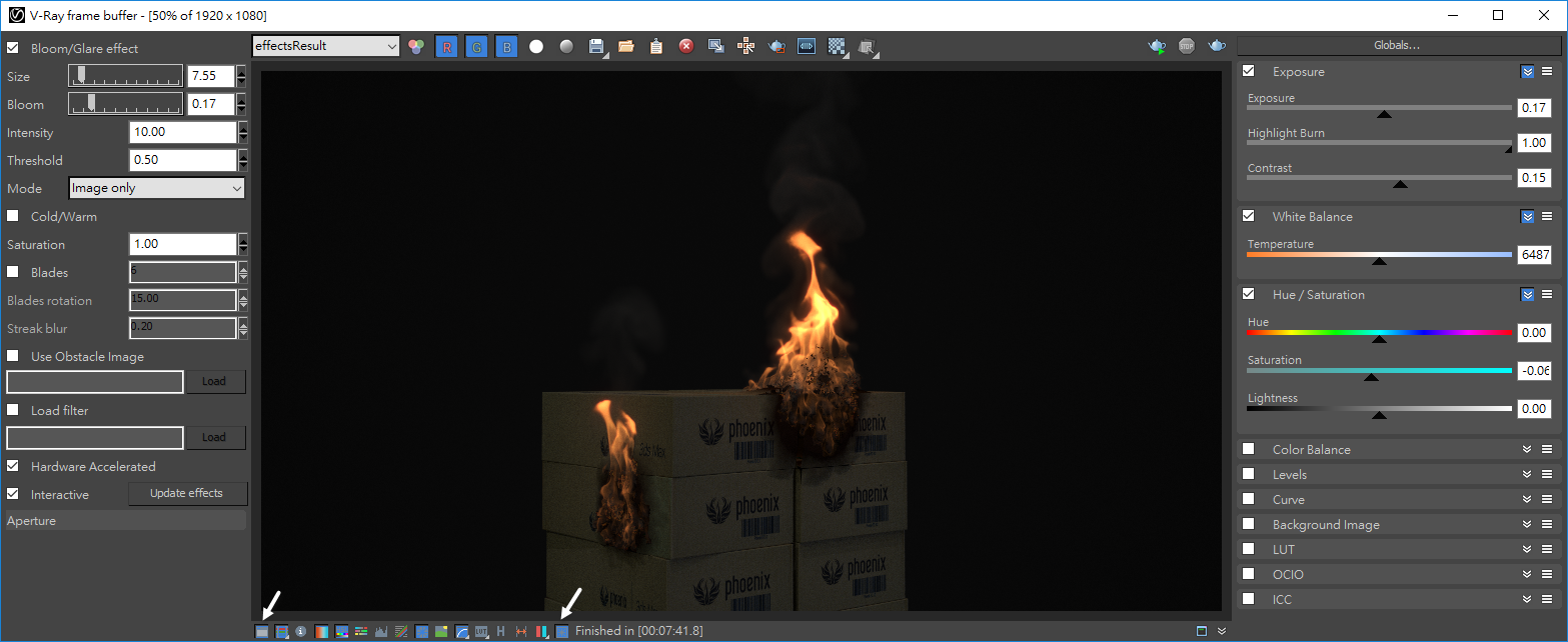
V-Ray Frame Buffer
Finally, we color correct and add lens effects within the V-Ray Frame Buffer. Click the icon on the toolbar below. On the left-hand side, enable the Exposure option and adjust the value until you get the right brightness and color. On the right-hand side enable the Bloom/Glare effect and change the amount until you get the right look.